I was cutting scrap steel when the pin spanner for my angle grinder vanished from my bench. Rather than stopping the job to find a replacement, I used two simple shop techniques to swap the disc using standard hand tools. You don’t need proprietary factory parts to change a wheel; just some leverage and basic gear.
Author: LifeKaki
⚡ Quick Guide: Unlocking a Grinder Disc Without a Key
📊 Technical Specifications & Parameters
| Standard Arbor Diameter: | 7/8 inch (22.23 mm) |
| Spindle Thread Pitch: | M14 x 2.0 |
| Flange Pin Hole Diameter: | 5 mm |
| Locking Mechanism: | Mechanical spindle pin |
| Disc Compatibility: | Cut-off, Flap, Wire |
📊 Project Overview
Difficulty Level: Easy
Time Investment: 5-10 minutes
Verdict: Self-service eliminates service fees and maintains project momentum.
Tools & Materials Used
🔧
Screwdriver set
AliExpress 🛒
🔧
Diagonal pliers
AliExpress 🛒
🔧
Abrasive sandpaper
AliExpress 🛒
🛠️
BUY ON ALIEXPRESS 🛒
Recommended
Angle grinder
Step-by-Step Replacement Methods
Positioning Screwdrivers for Torque Leverage
I unplugged the unit and depressed the spindle lock. I selected two medium screwdrivers and inserted the shafts into opposing flange nut holes. Steel shanks are necessary to prevent snapping under torque. I crossed the shafts to form a lever, providing mechanical advantage. I applied counterclockwise pressure until the thread friction released. The nut popped loose.
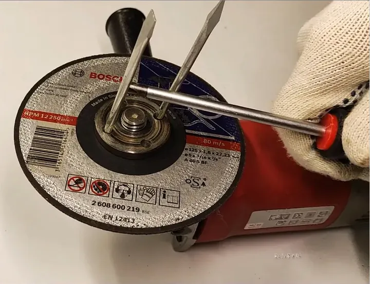
Removing Outer Flange and Loading New Disc
I unscrewed the flange nut by hand. I removed the spent wheel and cleared the arbor area of metal shavings. Debris in the seat can cause vibration and bearing damage. I placed the new wheel onto the flange shoulder, ensuring the label faced outward. The wheel seated properly.
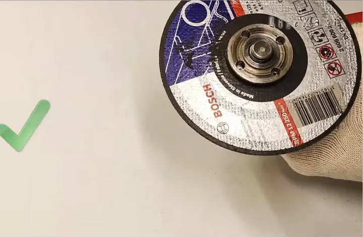
Aligning Flap Disc onto Spindle Arbor
I inspected the disc hub fitment against the inner collar. I dropped the flap disc onto the spindle and rotated it until it sat level. The fiberglass backing must be flush against the driving flange to prevent wobbling. I confirmed the clearance between the disc and the guard. Alignment was successful.
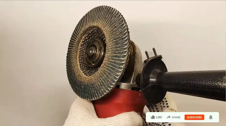
Removing Flap Discs via Palm Pressure Method
Sanding flap discs often hide the flange holes. I engaged the spindle lock and used my gloved palm to grip the disc edge. Friction allows turning the entire assembly. I applied steady pressure to unlock the threads. The assembly rotated free.
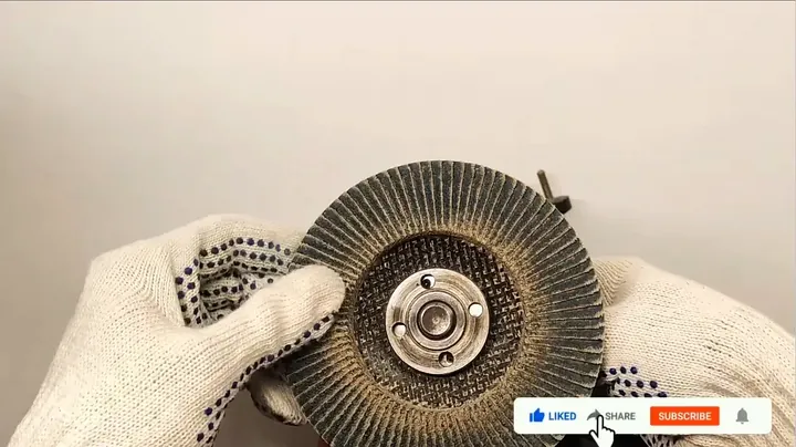
Checking Flange Orientation and Center Stepped Collar
I inspected the nut profile. One side features a stepped shoulder; the other is flat. I oriented the shoulder outward to clamp the disc correctly. Inverted installation prevents proper thread engagement. I threaded the nut until contact. Engagement was complete.
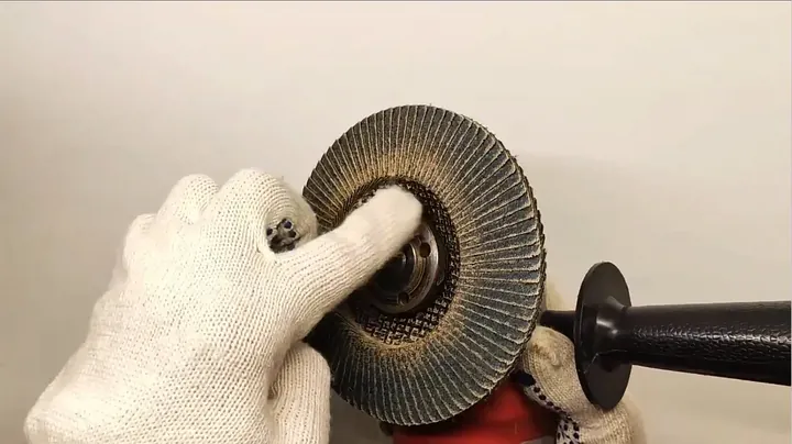
Tightening Retaining Nut Without Over-Torquing
I held the spindle lock and tightened the nut by hand. Excessive force is unnecessary. The tool self-tightens during operation due to motor rotation. Hand-tightening provides sufficient clamping force for safe use. The nut was secure.
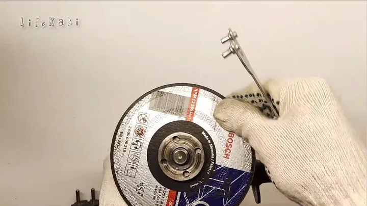
Final Spin Testing and Guard Safety Check
I released the spindle lock and rotated the disc by hand. I checked for guard clearance. I reconnected the power source. I activated the tool for ten seconds to monitor for vibration or alignment issues. The tool operated smoothly. Ready for use.
⚠️ CAUTION: SAFETY WARNING!
Disconnect power before service. Utilize protective gloves for handling abrasive components.
Summary & Tips
Missing spanner wrenches do not necessitate work stoppage. Screwdriver leverage serves as an effective alternative for nut removal. Leather-gloved palm pressure provides sufficient torque for flap discs. Avoid over-tightening; motor torque ensures secure seating during operation.
📋 FAQ
❓ Is hammering the nut an option?
Hammering damages hardware and housing. Screwdriver leverage is the preferred method for component integrity.
❓ Are spindle nuts reverse threaded?
Standard grinders utilize right-hand threads. Counterclockwise rotation unlocks the nut.
❓ Why do flap discs lock up?
High friction during operation increases torque on the flange. Palm torque is effective for removal.
Disclaimer: Content includes affiliate links. No compensated reviews included.
🛒 Useful Links & Products
🛠️
BUY ON ALIEXPRESS 🛒
Recommended
Cordless Grinder Cutting Machine




Leave a Reply