I’m taking on that exact challenge today: a full 40W soldering iron repair, which means I’ll be replacing a burnt-out heating element and installing a brand-new power cord. This isn’t just about getting the tool operational; it’s about understanding how these simple devices function and completing a repair that will truly last. I’ll open it up, remove the worn-out internals, and then wire in the new components, effectively bringing this essential workshop tool back to its prime. It’s a straightforward, hands-on fix that saves money and keeps a perfectly functional item from ending up in the landfill.
Author: LifeKaki
⚡ Quick Guide: How to Make It in 5-10 Steps
- Loosen retaining screw on electrical plug; disassemble housing.
- Measure new 40W heating element resistance.
- Route black wire through sleeve; feed all wires through yellow housing.
- Crimp ferrules tightly onto prepared wire ends.
- Attach yellow handle housing onto main power cable; secure with screws.
- Seat white cap into handle; tighten screw on metal soldering iron tip.
- Perform initial functional test on small project.
- Check tip temperature with infrared thermometer.
- Verify power consumption with meter.
📋 In This Article
- Technical Specifications
- Tools & Materials — what you need
- Initial Inspection and Plug Disassembly
- Inspecting the New Heating Element
- Routing New Wires
- Crimping and Organizing Internal Wires
- Managing Wires During Reassembly
- Final Wire Tucking and Handle Check
- Initial Functional Test with LED Project
- Final Power Consumption Verification
📊 Technical Specifications & Components
| Soldering Iron Power | 40W |
| Heating element | 40W compatible |
| New power cable | |
📊 Project Overview & Costs (USA Market)
Difficulty Level: Medium
Time Investment: DIY: 1 – 2 hours | Pro: 30 – 45 minutes
Verdict: DIY repair of a 40W soldering iron saves approximately in labor costs. This amount adequately covers replacement parts and additional tools.
Tools & Materials Used
• Wire Cutters
• Tweezers
🔧
Digital Infrared Thermometer
AliExpress 🛒
🔧
A830L Digital Multimeter
AliExpress 🛒
🔧
Universal Multifunctional Diagonal Pliers
AliExpress 🛒
🔧
Screwdriver Set For Gadgets
AliExpress 🛒
🛠️
BUY ON ALIEXPRESS 🛒
Recommended
Electric Soldering Iro
Step-by-Step Assembly & Testing
Initial Inspection and Plug Disassembly
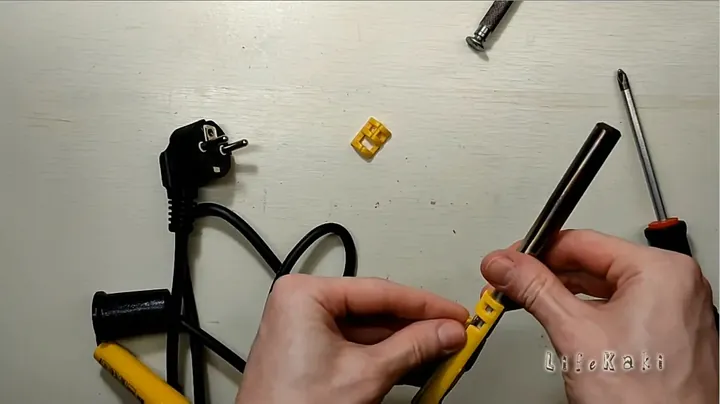
Starting this 40W soldering iron repair by giving the old tool a good once-over. First, I need to loosen that retaining screw on the black electrical plug. It’s usually a small Philips head, nothing too fancy. After that, I carefully disassemble the plug housing itself to expose the internal wiring; I need to see what’s going on inside there. My next move is to grab the multimeter and test the plug pins for continuity. This’ll tell me if I’ve got a dead short or an open circuit right at the entry point.
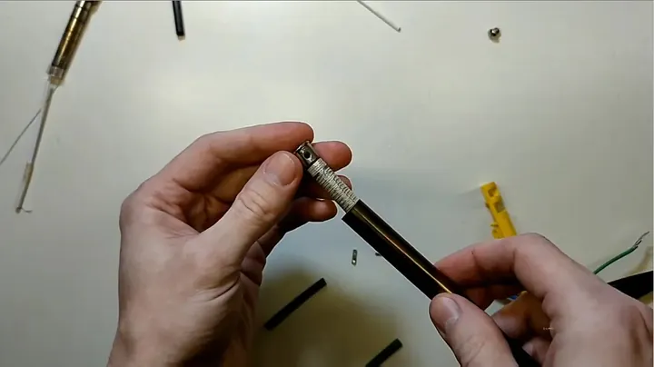
I’m also taking a moment to inspect the metal heating tube and the yellow housing, looking for any obvious cracks or charring. Then, I’ll carefully insert the metal tube into the yellow component, making sure it seats properly. Finally, I strip the white insulation from the internal wires, getting them ready for the next steps. Gotta be careful not to nick the copper strands. This initial check-up is crucial for diagnosing the problem right. You’d be surprised how often it’s just a simple plug issue.
Preparing Wire Connections
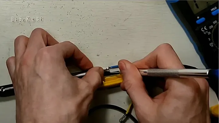
Getting those wires prepped and ready for solid electrical contact. My needle-nose pliers are out, and I’m crimping a fresh connector onto the blue wire. It’s all about making sure the insulation’s stripped just right, exposing enough copper for a secure grip. You don’t want a loose connection here; that’s just asking for trouble down the line, like arcing or intermittent power.
Using a proper crimp ensures a mechanically strong and electrically sound bond, much better than just twisting wires together. A good crimp means less resistance and better heat transfer through the new element. I’m applying firm, even pressure with the pliers, feeling the metal of the ferrule deform around the wire strands. If it feels too loose, or if strands poke out, I’m doing it again. A sloppy crimp will cause hot spots, and that’s a fast track to another failure. After the crimp, I give it a gentle tug test. It shouldn’t budge. This little detail makes all the difference for a durable repair.
Inspecting the New Heating Element
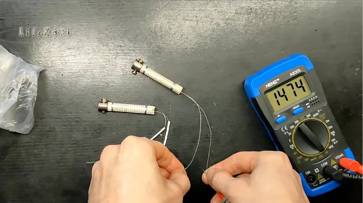
Now, it’s time to get a good look at the heart of this repair: the new heating element. I’m carefully unwrapping it from its protective packaging, making sure not to bend or damage those delicate wires. Before I even think about installing it, I need to verify its connection points on the metal tube assembly. Are they clean? Are they sturdy? This is where my multimeter comes in handy again.
I’m measuring the resistance of this new element. This reading tells me if it’s within the expected range for a 40W unit and if it’s healthy. If the resistance is way off, or if it shows an open circuit, I’ve got a dud right out of the box. A proper resistance value means it’ll draw the correct current and heat up as it should. Don’t skip this step; it saves you from putting a faulty part into your iron. Good to go.
Prepping Ferrules and Wire Ends
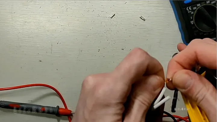
I’m getting down to the nitty-gritty of wire preparation. I grip the small metal ferrule firmly with my pliers, making sure it’s stable and ready for the wire connection. It’s essential to have these pieces organized on the workspace surface; a messy bench leads to mistakes. Next, I twist the two wire ends together, really tight, to ensure all the individual strands make solid contact. This twisting action compacts the wire, making it easier to insert into the ferrule and ensuring maximum conductivity. You want those strands to act as one solid conductor, not a loose bundle. This prevents stray strands from shorting out later or creating a weak point in the connection. It’s a small step, but it makes a big difference in the reliability of your electrical work. Don’t cheap out on the twist.
Routing New Wires
With the wire ends prepped, I’m moving on to routing them through the handle. First, I slide the black wire through its protective black sleeve. This sleeve is crucial; it adds an extra layer of insulation and strain relief, preventing wear and tear where the wire enters the housing. After that, I carefully feed all the wires through the yellow plastic component. It can be a tight fit sometimes, so a gentle hand and a bit of wiggling are key. I’m adjusting the wire positions inside that yellow housing assembly, making sure there’s no pinching or excessive bending. You want everything sitting neatly, not crammed in there. Proper routing prevents shorts and makes reassembly much smoother. Take your time here; rushing it could mean tearing out a connection. Looks good.
Trimming and Securing Wire Ends
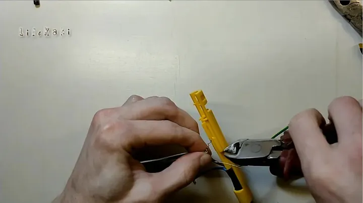
Now I’m fine-tuning the wire lengths before the final connections. I grab my sharp wire cutters and trim any excess wire length. You want just enough exposed wire to make a good, clean connection inside the ferrule, without having too much bare conductor hanging out. Then, I twist the wire pairs together for a solid, compact connection. This ensures all the strands are bundled tightly, which is key for reliability. Next, I insert the twisted wire end into the small metal ferrule. It needs to go all the way in, no copper showing outside the ferrule’s crimp area. I’m ensuring the wire is seated fully inside the ferrule before crimping. A proper seat means a stronger crimp and less chance of the wire pulling out or making poor contact. This precision prevents future headaches.
Crimping and Organizing Internal Wires
it’s time to make these connections permanent and tidy. I’m crimping the ferrule tightly onto the wire with my pliers. This isn’t just a squeeze; it’s a firm, deliberate action to ensure a robust mechanical and electrical bond. A weak crimp is a recipe for intermittent power or, worse, overheating. Once that’s done, I start arranging the green, white, and blue wires neatly inside the housing. Good organization is vital in tight spaces like this. You don’t want wires crossing unnecessarily or getting pinched when you close things up. Then, I twist the remaining wire connections securely together, making sure every strand is accounted for. This keeps the internal wiring clean and helps prevent any accidental shorts. Proper wire management isn’t just for looks; it’s for safety and longevity. Don’t skip this part.
Finalizing Crimp Connections
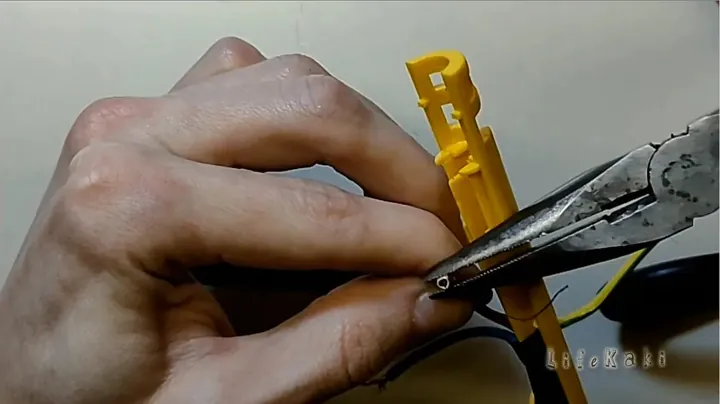
I’m on the home stretch with these crimps, finalizing the electrical path for the heating element. I crimp the last ferrule firmly onto its wire, applying solid pressure to ensure it’s tight. A good crimp feels secure, with no give or wiggle. This isn’t just about holding the wire; it’s about creating a low-resistance connection that won’t heat up under load. After that, I go back and check every single ferrule. I’m giving each one a gentle tug, making sure it’s crimped securely in place. Any loose connections will lead to trouble, either a dead iron or a fire hazard. It’s a quick but essential quality control step. This attention to detail means the iron will work reliably and safely. All good here.
Managing Wires During Reassembly
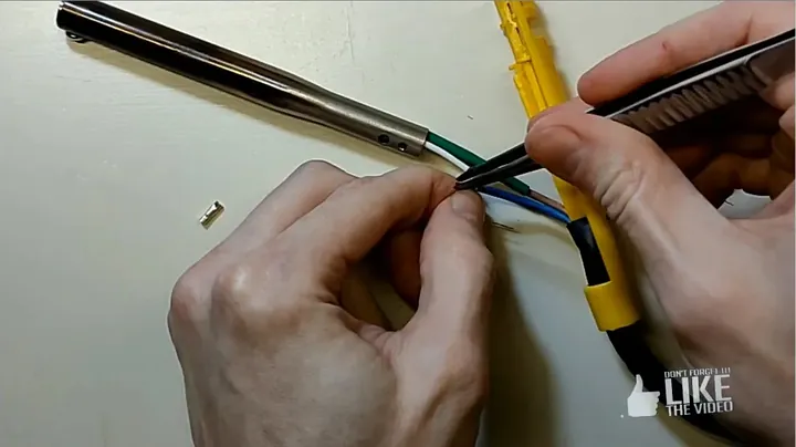
Now, I’m holding the metal tube steady while simultaneously managing all those internal wires. It’s a bit of a juggling act, trying to keep everything aligned and tucked away. You don’t want any wires getting caught or pinched as you bring the pieces together. I’m constantly checking my tools and components, making sure everything is organized on the table. A cluttered workspace can lead to dropped parts or incorrect assembly.
This stage demands patience; forcing parts together is a surefire way to break something. I’m gently guiding the wires, ensuring they sit in their designated channels without stress. It’s all about making sure there’s enough slack, but not too much, to prevent strain when the handle is fully assembled. This careful management ensures a clean internal layout. Take your time.
Attaching the Handle Housing
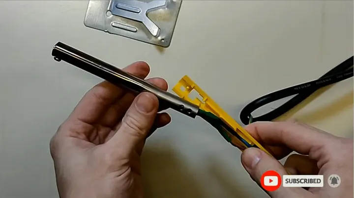
The internal wiring is sorted, so now it’s time to button things up. I carefully push the yellow housing onto the main power cable, making sure it slides on smoothly. Then, I align the metal heating tube with the yellow housing assembly. This alignment is critical; everything needs to mate up perfectly for the iron to be sturdy. Next, I insert the small screw into the yellow housing hole. This screw is the first point of securing the assembly.
I’m tightening that small mounting screw just enough to hold it firmly, but not so tight that I strip the plastic. Over-tightening is a common mistake that can crack the housing. Finally, I install the second screw into the yellow plastic component, completing the main handle assembly. Two screws mean it’s locked tight. This ensures the handle is solid and won’t wobble during use.
Final Wire Tucking and Handle Check
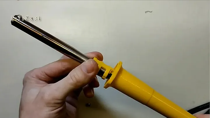
Before I put the very last piece on, I’m doing a final check of all the internal wires. I need to verify that every single wire is tucked away safely, with no exposed copper or potential pinch points. This is a critical safety step; stray wires can cause shorts or even electrocution. I’m holding the yellow handle firmly, giving it a good feel to ensure everything inside feels stable and secure. No rattling, no loose parts.
This physical inspection confirms the integrity of my assembly. You want that handle to feel solid in your grip, like a new tool. It’s all about confidence in your repair. If anything feels off, I’d open it back up and recheck the wiring. Looks good to go.
Securing the Handle Cap and Soldering Tip
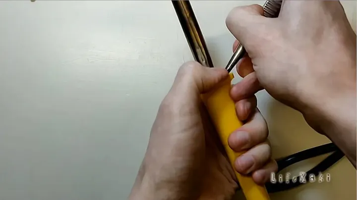
Now for the final bits and pieces of the handle assembly. I’m using a small tool to carefully seat the internal component correctly within the handle. It needs to click into place without being forced. I’m also ensuring the power cord exits the handle without any undue strain; a good strain relief prevents the cable from breaking where it enters the tool. Then, I insert the white cap into the end of the handle.
This cap often holds the cord securely and provides a finished look. I push the cap flush using my tweezers for precision, making sure it sits perfectly even with the handle’s surface. A flush fit means fewer snags and a more professional finish. Lastly, I tighten the screw on the metal soldering iron tip. This screw holds the tip firmly in place, ensuring good heat transfer from the element. It’s all buttoned up.
Initial Functional Test with LED Project
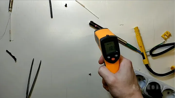
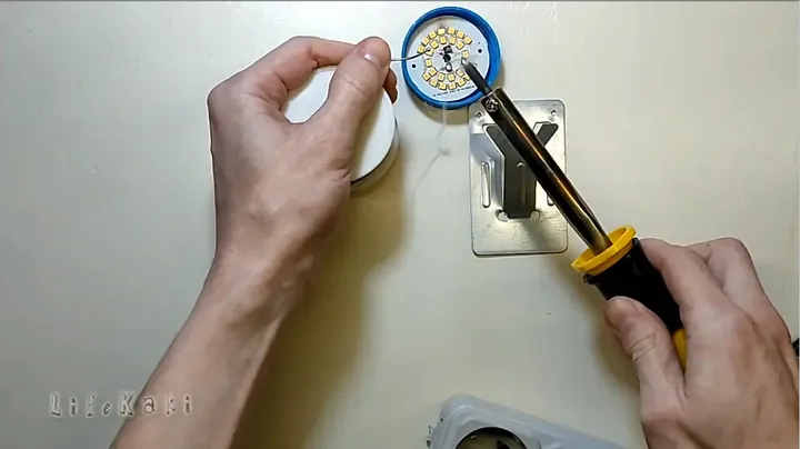
With the soldering iron all reassembled, it’s time for the moment of truth: a functional test. I’m not just going to plug it in and hope for the best; I’m going to test the iron near my LED light board project. This gives me a real-world scenario to see if it heats up and melts solder properly. I plug it in and watch for the tip to come up to temperature. Does it get hot quickly? Is there any smoke or strange smells? These are all indicators of how well the new element is working. While waiting, I make sure to place the iron on its stand. That’s just good practice, keeping a hot tip away from my bench. This initial test tells me if the core repair was successful. It’s heating up nicely.
Final Power Consumption Verification
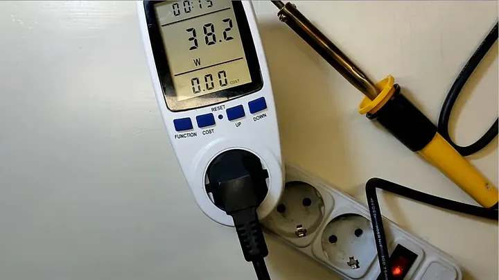
The iron’s working, the tip’s hot, and I’ve made some test joints. My final step is to verify its power consumption on the meter for safe operation. This check confirms that the new heating element isn’t drawing excessive current and that all my wiring is correct. If the wattage is way off, it could indicate an issue with the element or a short somewhere. A stable, expected power draw means the iron is running efficiently and safely, just like it should. This last check gives me peace of mind that the repair is solid. This iron’s ready for more projects. Definitely save this video for your future repair reference; it’s a repeatable fix.
⚠️ CAUTION: SAFETY WARNING!
Always unplug the soldering iron before any repairs. Electrical work presents hazards. Consult a qualified electrician or seek professional assistance if uncertain about any step. Ensure all connections are secure and properly insulated to prevent electrical shorts or shocks.
Summary & Tips
Bottom line: my old 40W soldering iron is back in business, heating up like a champ with that new element and cord. This fix proved that a little elbow grease and the right parts can revive a tool, saving it from the landfill. It’s a solid repair, and it feels good to get a reliable iron back on the bench without dropping cash on a brand new one.
📋 FAQ
Is it worth repairing a cheap 40W soldering iron?
Yes, repair is often cost-effective. Heating elements and power cords are typically inexpensive. If the handle remains functional, replacement parts extend tool lifespan and reduce waste.
What’s the most common reason a soldering iron stops heating?
The primary cause is a failed heating element due to wear. Another common issue is a broken power cord, particularly at stress points near the handle or plug. Both are manageable repairs.
Can I use any heating element for my 40W soldering iron?
No, heating element wattage must match the soldering iron’s rating. Incorrect wattage leads to suboptimal performance or safety hazards, including overheating. Adherence to specifications is crucial.
Disclaimer: I purchased all tools for this guide with my own money to ensure an unbiased review. This post contains affiliate links, meaning I earn a small commission if you make a purchase at no extra cost to you.
🛒 Useful Links & Products
Electric Soldering Iro
🛒 BUY ON ALIEXPRESS




Leave a Reply