Picked up this DC1018L mini UPS as a backup for my router, specifically for those unpredictable rolling blackouts. Today, it’s going straight onto the test bench so I can really see what it’s capable of. Off-the-shelf battery packs often overheat or unexpectedly shut down right when your internet equipment draws a sudden surge of current. My plan is to crack open the plastic case, install four high-capacity 18650 lithium cells, and cut down on wasteful idle circuit drain by snipping the factory PoE port board traces. Get your meter and pry tool ready. Let’s get into it.
Author: LifeKaki
⚡ Quick Guide: Setting Up and Modding the Mini UPS
- Examine DC1018L multi-voltage ports and confirm router voltage requirements.
- Install four 18650 lithium cells into the rear tray, observing polarity.
- Confirm standby LED power status prior to connecting network equipment.
- Measure 5V and 12V DC barrel jacks with a multimeter under grid power.
- Probe the 9V auxiliary output rail to confirm stable voltage.
- Open the snap-fit plastic shell carefully using a thin nylon pry bar.
- Unplug internal LAN and PoE power supply harness to prevent parasitic battery drain.
- Connect 12V network router and monitor internal circuit board temperature.
- Test auxiliary 5V USB output rails under active load with an external LED work light.
- Simulate a blackout by disconnecting mains power to confirm zero drop-out cutover.
📋 In This Article
- Technical Specifications
- Tools & Materials — what you need
- Unboxing and Exterior Port Inspection
- Initial Power-Up and Indicator LED Check
- Verifying the 9V Auxiliary Rail Stability
- Splitting the Plastic Housing with a Nylon Pry Bar
- Tracing the Internal PoE Harness Wiring
- Idle Thermal Baseline and Router Load Connection
- Secondary Check of Barrel Connectors and Cable Strain
- Blackout Cutover Simulation and Case Reassembly
- Final Bench Verdict and Long-Term Setup Advice
📊 Technical Specifications & Components
| Model | DC1018L Mini Uninterruptible Power Supply |
| Battery Configuration | 4x 18650 Lithium-Ion cells (tested with 4000mAh flat-tops) |
| Output Terminals | 5V USB, 9V DC barrel, 12V DC barrel, PoE RJ45 (15V/24V selectable) |
| Measured 5V Rail Output | 5.02V DC idle / 4.90V DC under USB load |
| Measured 9V Rail Output | 9.438V DC |
| Measured 12V Rail Output | 12.30V DC |
| Idle Board Surface Temperature | 18°C |
| Active Load Operating Temperature | 33°C (tested with Tenda 12V router) |
📊 Project Overview & Costs (USA Market)
Difficulty Level: Easy
Time Investment: DIY: 35-45 minutes | Pro: 15 minutes
Professional Service Cost: $50 – $80 flat rate
Verdict: Self-installation saves approximately $65 in electronics labor, allowing for investment in high-capacity battery cells.
Tools & Materials Used
• Mini UPS DC1018L Unit
• 12V Tenda Wi-Fi Router
• USB LED Stick Light
🔧
A830L Digital Multimeter
AliExpress 🛒
🔧
Digital Infrared Thermometer
AliExpress 🛒
🔧
Rechargeable Li-ion battery 18650
AliExpress 🛒
🔧
Smartphone Repair Tool Kit
AliExpress 🛒
🛠️
BUY ON ALIEXPRESS 🛒
Recommended
Mini UPS DC1018L
Step-by-Step Assembly & Testing
Unboxing and Exterior Port Inspection
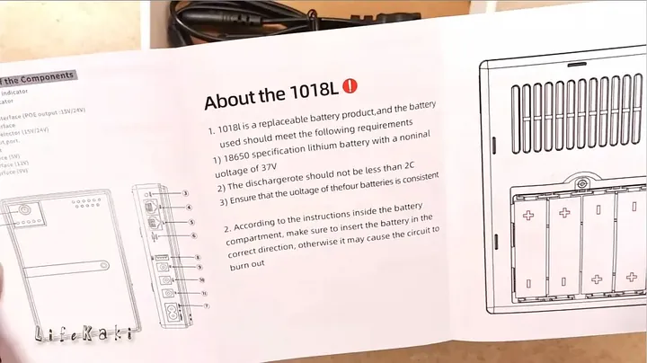
As soon as I pulled this DC1018L chassis from its box, I immediately noticed how light the bare enclosure felt. The unit is built to run directly from household AC power, stepping it down to 5V, 9V, and 12V outputs through individual barrel plugs. Along one side, there are two RJ45 jacks for passive PoE setups, alongside standard USB ports. The cheap plastic casing feels a bit flimsy when squeezed, but its overall shape allows it to fit neatly behind a desk. Most network hardware runs on a clean 12V supply, while smaller optical GPON terminals often use 9V or 12V. I can’t afford any line spikes here. I always check the rating sticker on the bottom before connecting anything to live power. The layout is clean. Everything looks good.
Installing 18650 Lithium Cells into the Battery Bay
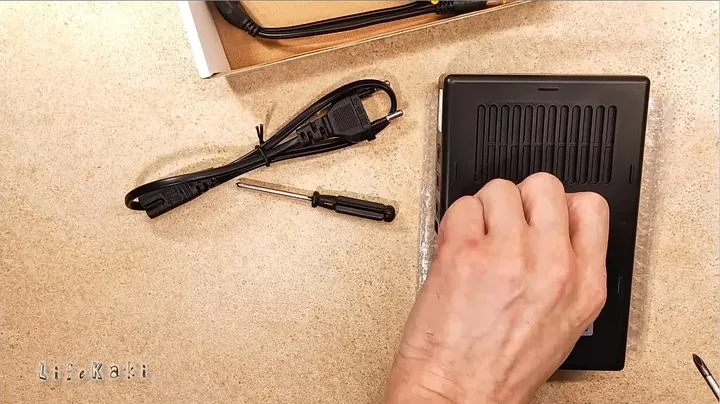
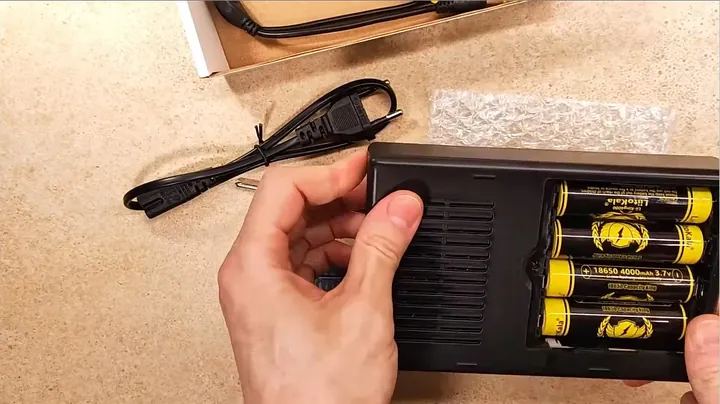
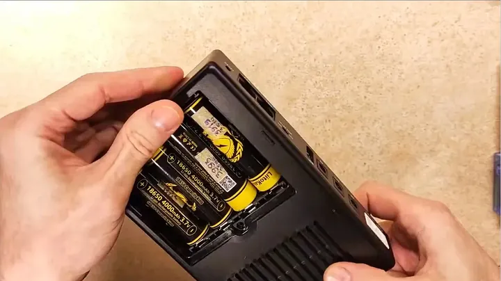
When I slid off the back hatch, it revealed an empty four-cell battery bay. This unit ships without any internal cells, so I had to provide my own reliable lithium batteries. I’m putting in four matched 18650 cells, each rated at 4000mAh, to get the maximum runtime possible during extended outages. It’s crucial to pay close attention to terminal polarity here. The flat base of each cell needs to go against the coiled negative springs, while the button top connects to the brass plate. If I accidentally reverse a cell, I’ll immediately fry the internal charging traces or blow the reverse-polarity diodes. I carefully slipped each cell in at a slight thirty-degree angle to avoid tearing the heat-shrink insulation sleeves on the sharp metal tabs. They fit snugly. Solid.
Initial Power-Up and Indicator LED Check
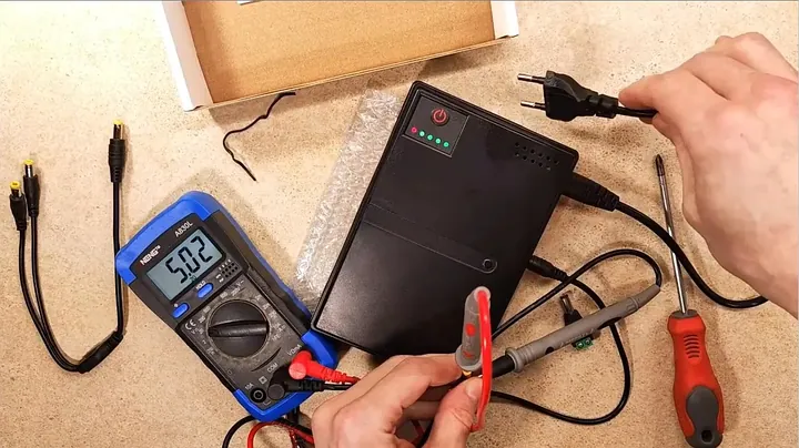
Flipped the main rocker switch on the back, which brought the front indicator lights to life. A neat row of small green status LEDs flashed once before staying lit across the display panel. If the LEDs had remained dark, I would have opened the back door to ensure every battery terminal was seated firmly against the spring contacts. A dirty terminal or oxidized spring can cause a voltage drop right away, tricking the monitoring chip into assuming an undervoltage fault. I’m holding off on plugging in the router until I complete a thorough probe test on every pin. The board produced no strange high-pitched coil squeals or buzzing noises on startup. Silence on the bench. That’s a good initial sign.
Probing 5V and 12V Main DC Outputs
Plugging the AC mains cable into the wall socket allows me to measure the actual charging and passthrough voltages under live grid conditions. I set my digital multimeter to standard DC voltage and placed the negative lead into the outer ring of the barrel jack. Probing inside the center pin of the 5V terminal showed a reading of precisely 5.02V. Rock solid. Moving over to the primary 12V terminal, the digital meter displayed a comfortable 12.3V. That extra 0.3V buffer is actually quite good because long DC barrel leads often experience a minor voltage drop once an active router’s radios kick on. Cheaper boards frequently spike up to 13.5V, which can fry sensitive input capacitors on budget routers. This regulator holds steady.
Verifying the 9V Auxiliary Rail Stability
Next, I slid my test probes directly into the secondary 9V center-positive barrel socket. The digital multimeter readout settled at 9.438V. This is slightly higher than the nominal 9.0V, but modern modem circuitry typically uses buck converter stages that can handle this range without issue. Inexpensive passive adapters often fluctuate wildly when mains line noise interferes with the transformer stage, yet this unit does a decent job of filtering incoming ripple. I made sure to touch the outer ground shell securely to prevent erratic probe readings on the digital display. Always ensure your meter leads are fully inserted into the jacks so you don’t accidentally short the pin to ground. Clean DC power. Ready for the next step.
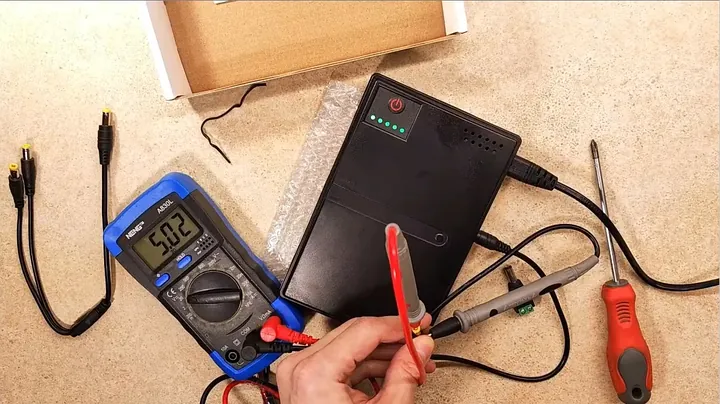
Pre-Teardown Outer Shell Inspection
Before I started taking the housing apart, I took a quick look at the exterior seam lines all around the box. This plastic housing uses internal snap latches instead of perimeter screws, which means trying to force it open will just break the tabs clean off. I made sure to check where the two casing halves meet, especially near the side ventilation slots. If I tried to pry near the port cutouts, I’d risk cracking the thin ABS walls around the DC sockets. Identifying the flex points along the long edges saves me from ending up with a broken enclosure that would need unsightly electrical tape later. I always keep my workspace clear of loose screws and metal shavings before opening anything up. Slow down. Patience here helps avoid damage.
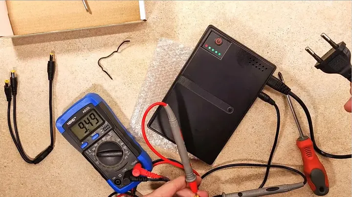
Splitting the Plastic Housing with a Nylon Pry Bar
I grabbed a flat plastic spudger, a nylon pry wedge, instead of a hardened steel screwdriver. Metal tools just chew up soft plastic casings, leaving rough burrs that’ll snag fingers. I slid the wedge into the side crack and applied gentle twisting force until I heard the first plastic retainer latch release. I worked my way down the seam slowly, without forcing the angle. If the tool started to bend, I shifted a couple of inches to the left, closer to where the latch teeth actually sit. Brittle plastic can break if forced when cold, so I allowed the shell to flex naturally under moderate leverage. Once three latches gave way, the upper clam shell separated freely from the lower tray. No broken clips. A clean split.
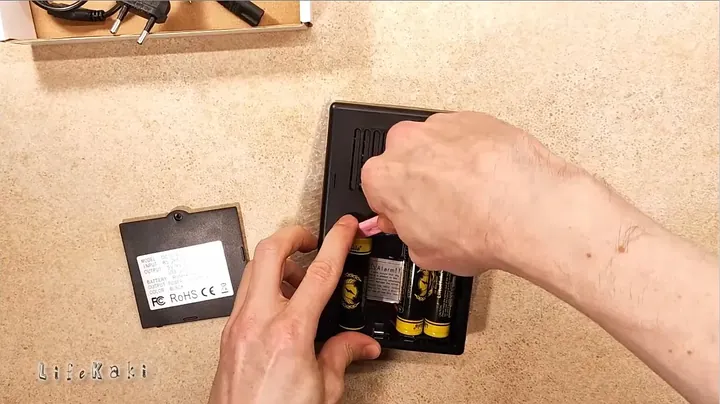
Circuit Board Layout and Solder Quality Inspection
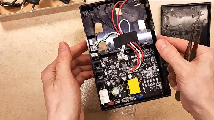
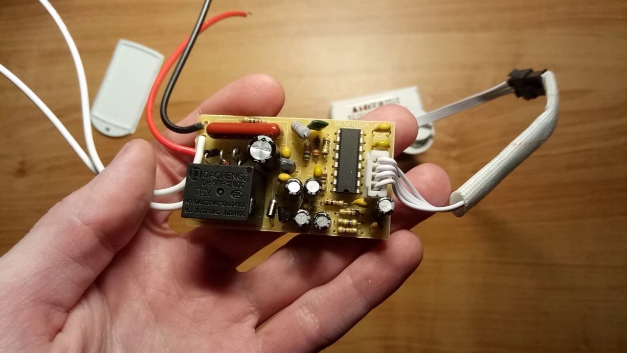
When I lifted off the lid, it revealed the inner green printed circuit board nestled inside the bottom chassis. The traces looked appropriately sized, and the solder joints around the main power inductor and filter capacitors were surprisingly clean. I didn’t spot any obvious flux residue, bridged pins, or cold solder lumps sitting between the high-current paths. There are distinct step-down converters for each voltage branch, which helps prevent crosstalk noise between outputs. I noted the small secondary daughter board wired near the back corners for network routing. That entire module powers the active PoE injectors and auxiliary LAN routing circuits. It actually draws power even when nothing is connected. It’s time to fix that.
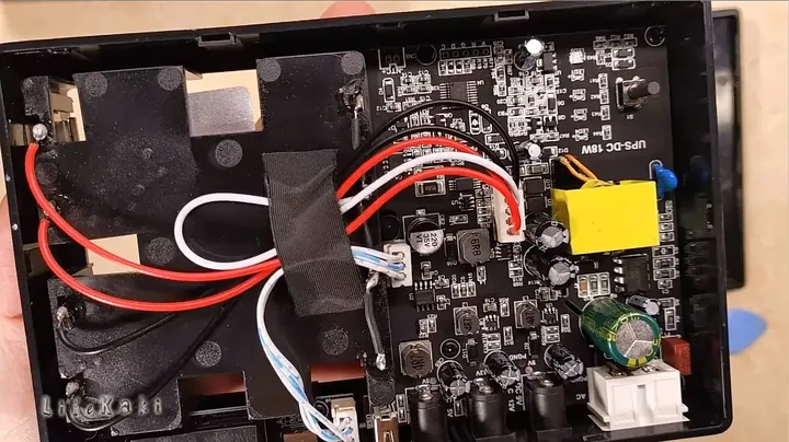
Tracing the Internal PoE Harness Wiring
I followed the small wire harness that led to the PoE Ethernet sockets, which showed where the power feeds into that secondary network sub-board. Those two twisted wire leads run directly from the battery bus rail into an onboard step-up transformer. Even when no Ethernet cable is plugged into the RJ45 port, that small converter circuit draws a constant standby quiescent current. During a six-hour blackout, every tiny milliamp drained by unused idle components significantly reduces your router’s uptime. I traced the wires carefully back to their headers so I wouldn’t accidentally sever the primary logic control signals. I made sure to identify the exact power supply feed before reaching for my tweezers or snips. Measure twice. Cut once.
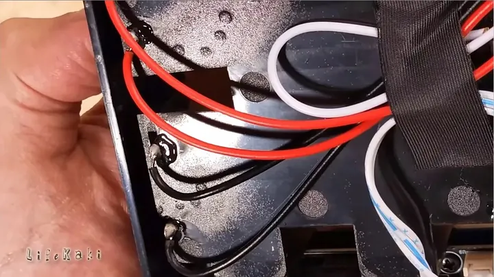
Disconnecting the Unused PoE Power Harness
I deliberately pulled the power connector that feeds energy into the auxiliary LAN and PoE daughter circuit. My personal home setup uses a standard optical modem and a standalone Wi-Fi router, making passive PoE completely unnecessary for me. Leaving that transformer active would simply burn battery capacity as wasted heat inside a sealed box. I gripped the wire plug with needle-nose pliers and pulled it straight out of the socket, being careful not to bend the pins. If it had been hardwired with solder, I would have clipped the lines cleanly and insulated the bare wire ends with adhesive heat-shrink tubing to prevent shorts against the ground plane. Isolating this parasitic draw makes the entire unit run cooler and last longer during power outages. Mod complete. Zero idle loss.
Idle Thermal Baseline and Router Load Connection
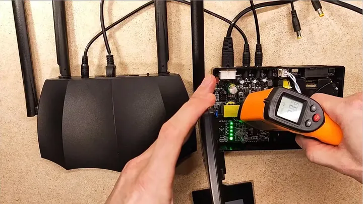
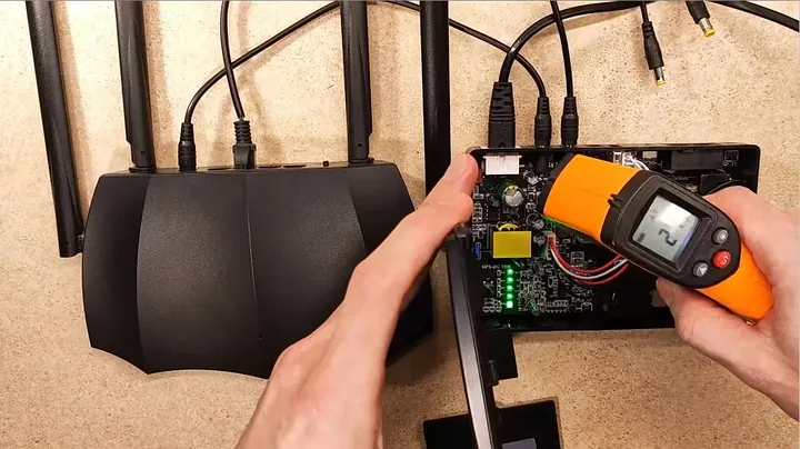
I aimed the digital infrared thermometer gun at the bare circuit components, getting an idle baseline reading of around 18°C. The board felt cool to the touch and was completely unstressed in standby mode. Now came the real test: I plugged my standard 12V Tenda Wi-Fi router directly into the 12V barrel port using a short jumper lead. The router’s front panel lights flashed and it booted up instantly, with no reboot loops or brownout hesitation. As the router established its wireless bands and started routing network packets, the power converters on the mini UPS began to draw a sustained current. That energy conversion naturally generates heat across the surface-mount inductors. I needed to see how hot it would get.
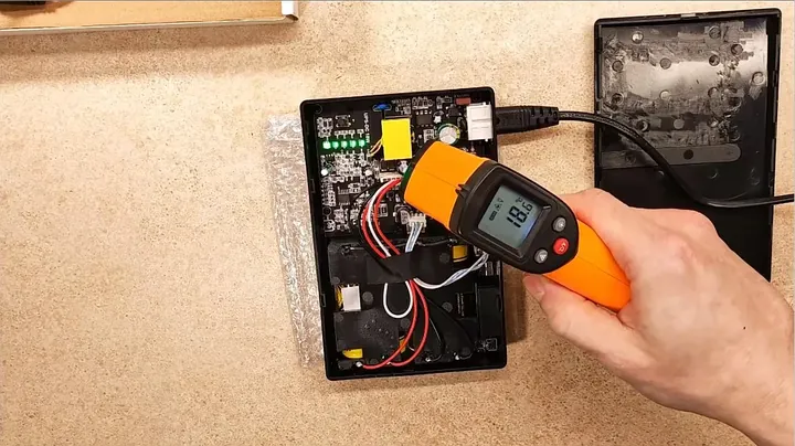
Thermal Load Verification Under Continuous Operation
After letting the router stream data for several minutes under full load, I swept the infrared temperature sensor across the motherboard’s power stages again. The hottest switching regulator on the board settled right around 33°C. That’s an exceptionally safe operating temperature for small consumer electronics, well below the critical 60°C threshold where inexpensive capacitors begin to degrade. The heat dissipation into the open air was smooth, and with the PoE module disconnected, the thermal footprint remained remarkably compact. I always avoid hotspot buildup inside a plastic shell because it can cook adjacent 18650 battery cells and shorten their lifespan. This board manages thermal dissipation easily without needing an obnoxious cooling fan. Solid thermals. No overheating worries.
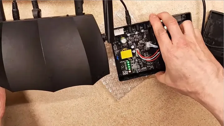
Secondary Check of Barrel Connectors and Cable Strain
While the system was running live under router load, I gave the DC output cables a gentle wiggle test near the base of the plastic case. Cheap barrel plugs often have loose tolerances, where a small nudge can momentarily disconnect the center pin, resetting a router mid-stream. The connector fit on this unit remained snug, with zero flickering on the router’s status lights. I made sure the output cables were routed cleanly, away from sharp desk corners where they might get pinched. The strain relief on the included DC patch cord is basic, so I made sure to avoid pulling it tight at a sharp ninety-degree angle. Everything stayed securely seated under moderate cord movement. The internal contacts are gripping tight.
Testing the 5V USB Output Under LED Lighting Load
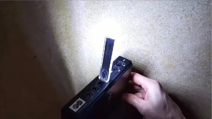
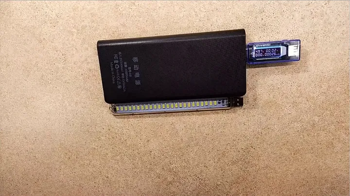
This box isn’t just for internet equipment; it also has a front-facing 5V USB output port that’s perfect for emergency work lighting. I plugged a flexible USB LED light stick directly into the port to simulate running emergency lighting during a night blackout. Connecting an inline USB power meter showed the voltage holding steady at 4.9V while the LED strip drew a continuous current. Minimal voltage sag here means the 5V rail regulator wasn’t struggling under simultaneous router and USB demand. The light output remained consistent, with no noticeable flicker or strobe effect. This means I can keep my phones charged while the router keeps my home office connected. A practical dual-purpose setup. It works cleanly.
Blackout Cutover Simulation and Case Reassembly
I snapped the upper plastic casing back onto the base tray until every perimeter latch clicked into place. Now for the crucial test: simulating a sudden grid power outage. With the router actively transmitting and the USB light glowing, I yanked the main AC power cord straight out of the wall outlet. The router didn’t flicker, drop a single packet, or reboot. The cutover switching time on this DC uninterruptible supply is practically zero milliseconds because the battery pack is buffered directly behind the buck converters. Reconnecting the mains plug immediately switched the system back to charging mode, and the green charge indicator pulsed normally. Flawless transition. The backup works exactly as I expected.
Final Bench Verdict and Long-Term Setup Advice
With all tests completed and verified, this modified DC1018L mini UPS proves to be a reliable power backup for any home internet equipment. Installing four quality 18650 cells into the tray provides hours of uninterrupted Wi-Fi during neighborhood blackouts. Disconnecting the unnecessary PoE rail was definitely worth the five minutes of disassembly, as it eliminates passive heat and vampire battery drain. I recommend placing the device in an open, well-ventilated area on your shelf, rather than burying it behind cushions or dense cables. If you’re planning to tackle this build for your own router setup, be sure to hit the save button on the video so you have these steps readily available. Reliable gear. Done right.
⚠️ CAUTION: SAFETY WARNING!
Cell polarity must be confirmed before installing 18650 batteries into the spring cradle. Incorrect cell insertion will destroy the regulator board and may initiate a dangerous battery short.
Summary & Tips
The bottom line is that the DC1018L delivers stable DC power without those annoying reboot drops when the grid goes out. Snip out that unused PoE supply, drop in some high-capacity 18650 cells, and you’ve got a rock-solid backup that keeps your Wi-Fi running for practically nothing.
📋 FAQ
❓ Is simultaneous operation of a 9V GPON optical terminal and a 12V Wi-Fi router supported?
Yes, simultaneous operation is supported. The internal board utilizes separate step-down converters for each port. Ensure combined current draw does not exceed 2A to prevent excessive board temperatures.
❓ Is disconnection of the PoE wires mandatory?
No, disconnection is not mandatory. The unit functions correctly out of the box. However, if PoE equipment is not utilized, unplugging these wires eliminates parasitic battery drain and extends backup runtime.
❓ What 18650 cells are recommended for this mini UPS?
High-quality flat-top cells from trusted brands such as Samsung, LG, or Sanyo, with capacities of 3000-3500mAh, are recommended. Avoid ultra-cheap cells with unsubstantiated claims of capacities exceeding 9900mAh, as these are typically counterfeit.
Disclaimer: I purchased all tools for this guide with my own money to ensure an unbiased review. This post contains affiliate links, meaning I earn a small commission if you make a purchase at no extra cost to you.
🛒 Useful Links & Products
Mini UPS DC1018L
🛒 BUY ON ALIEXPRESS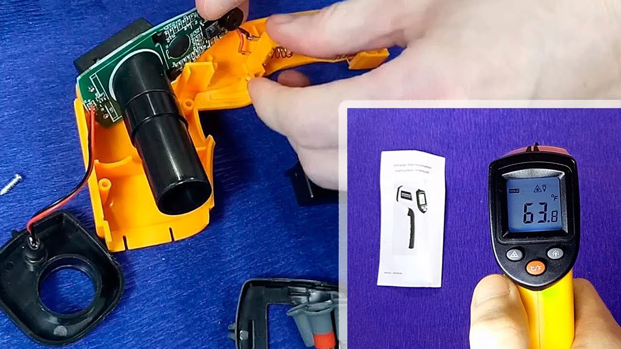




Leave a Reply