Got a dead 12V tire inflator on the bench. Stopped mid-job. Most people toss these things the second they quit — but nine times out of ten the motor is fine. What actually dies is the copper wire right where it enters the housing. Vibration, heat, and yanking the cigarette plug around all fatigue the strands at that exact spot. Stripped the case, found the break with a multimeter, soldered in a proper joint, and put it back under load.
Author: LifeKaki
⚡ Quick Guide: Fix a Dead 12V Car Compressor
- Pop the plastic housing open. Get at the wiring.
- Buzz out the circuit with a multimeter. Switch and motor leads.
- Find the broken copper under the strain relief. That’s your culprit.
- Strip the wire. Tin both ends with a soldering iron.
- Solder the 12V lead back onto the motor lug. Solid joint.
- Shrink tube the joint. Route the cable away from moving parts.
- Put the cylinder, gearbox, and motor back in the chassis.
- Power it up. Watch the pressure gauge climb.
📋 In This Article
📊 Technical Specifications & Components
| Input Voltage | 12V DC nominal |
| Power Source | Car 12V accessory socket / battery clamp |
| Motor Type | Brushed DC high-torque motor |
| Pressure Gauge | Analog mechanical dial (0-150 PSI) |
| Wiring Type | Multi-strand flexible copper core |
| Solder Joint | Rosin core tin-lead / lead-free compatible |
📊 Project Overview & Costs (USA Market)
Difficulty: Easy. Basic soldering and continuity testing.
Time: DIY: 30-45 mins | Pro: 15 mins
Tools & Materials Used
🔧
A830L Digital Multimeter
AliExpress 🛒
🔧
Automatic Wire Stripper Tool
AliExpress 🛒
🔧
Universal Multifunctional Diagonal Pliers
AliExpress 🛒
🛠️
BUY ON ALIEXPRESS 🛒
Recommended
Electric Soldering Iron
Step-by-Step Compressor Repair & Diagnostic
Opening the Plastic Housing
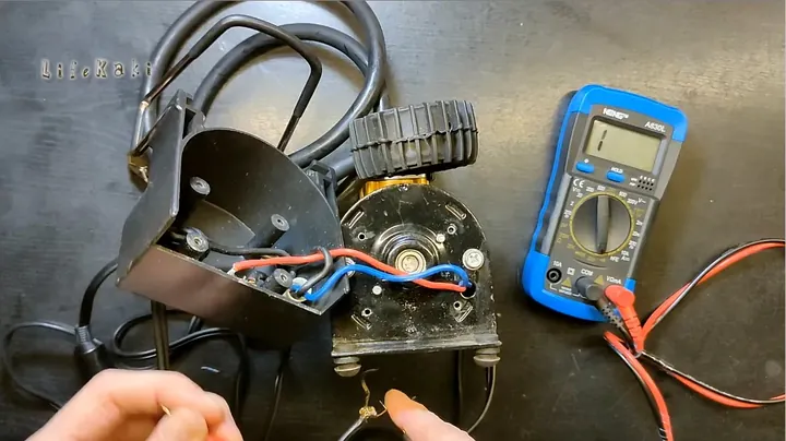
Two-piece plastic shell. Split it and you’re looking right at the piston cylinder and the brushed DC motor. Back out the perimeter screws with a proper-fitting — slip and you’ll strip the head, then it’s a whole afternoon. Go slow. Car plastic gets brittle after years of heat cycling in a trunk. Don’t pry along the seam until every screw is out. When the halves come apart, watch the toggle switch leads — they love snagging on the inner alignment ribs. The power cord runs through a molded rubber strain sleeve. That sleeve takes all the abuse. Mine looked fine on the outside, but the cord bent unnaturally limp right at the neck. That’s the tell.
Visual Inspection of Power Leads
Trace the positive and ground wires toward the motor tabs. Start at the high-flex point where the cord exits the grommet. Copper inside cheap automotive wire fatigues from vibration long before the outer PVC shows a scratch. Give the harness a firm pull. If the insulation stretches like soft rubber, the strands inside have already separated. Peel the sheath back half an inch and look at the core. Also check the rocker switch terminals for cracked solder or loose spade connectors.
Multimeter Continuity Test
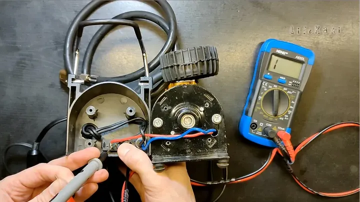
Multimeter on continuity buzzer. Touch the probes first to make sure the meter’s alive. Then clamp one lead to the center tip of the 12V plug and trace down through the rocker contacts to the motor brush tab. Nothing. Silence. That missing beep is your open circuit. Now flex the wire at the strain relief while watching the meter — if it crackles or beeps, you’ve found the break. Mine was right at the neck, exactly where I suspected.
Pinpointing the Wire Fracture
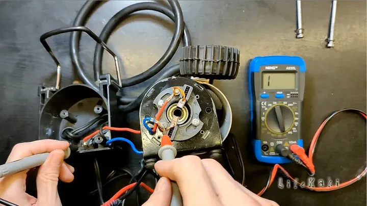
Time to cut out the fatigued section. Side cutters, two inches back from the kink. Strip it clean. Bright copper or bust. If the wire turns black or green inside, keep trimming until you hit shiny metal — solder won’t stick to oxidized copper without aggressive flux. The original solder mound on the motor lug looked fine, but the strands right behind it had failed. Good copper secured. Grab the iron.
Tinning the Wire and Terminal
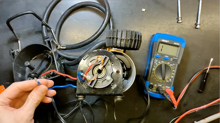
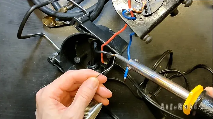
Iron to 350°C. Strip a quarter inch with the automatic stripper so you don’t nick the inner strands. Twist the bare copper tight between your fingers. Touch a drop of rosin-core solder to the tip to make a thermal bridge. Bring the tip against the copper and feed in solder — capillary action should pull it through every strand. Tin the motor lug the same way. Pre-tinning both surfaces is what prevents cold, crusty blobs later.
Soldering the 12V Connection
Hold the tinned wire against the motor tab. Steady hand or a pair of locking forceps. Press the chisel tip across the junction until both tinned surfaces turn liquid and merge into one pool. Lift the iron and hold the wire dead still for three full seconds while it solidifies. Never blow on cooling solder — that rapid quench wrecks the crystal structure and the joint fails. Good joint looks mirror-bright and concave. Bad joint looks frosty or peaked. Give it a firm tug to make sure it’s solid. That held.
Heat Shrink and Strain Relief
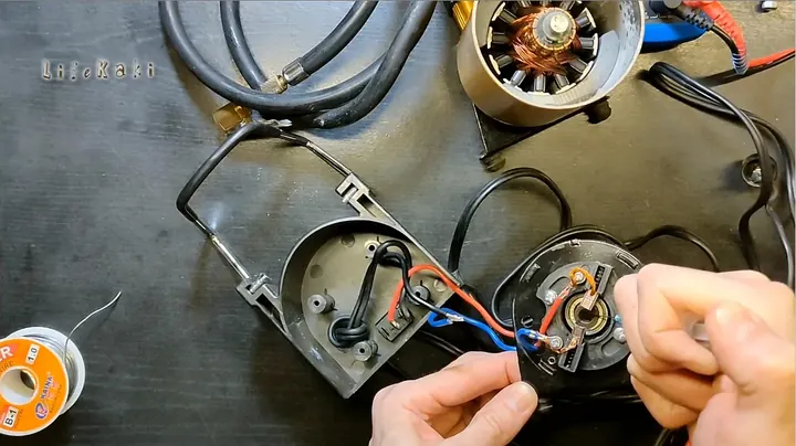
Bare electrical contact inside a metal compressor shell = short to ground. Slip a piece of polyolefin heat shrink over the soldered lug. Run the iron barrel near it until it shrinks tight. Then anchor the cable with a zip tie just inside the entry wall. That zip tie stops external cord tension from pulling on the solder joint. Clean routing pays off. Trust me.
Bench Cleanup and Workspace Check
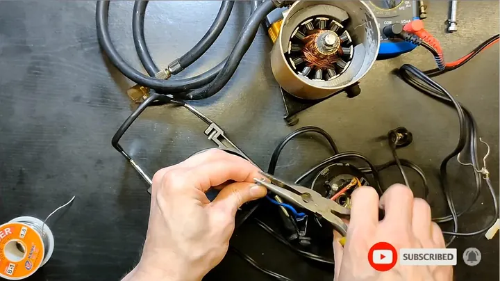
Stop and clear the bench before closing it up. Loose copper clippings are the worst. One stray strand inside an open DC motor can bridge the commutator bars and fry the armature. Brush down the work mat. Check the gear assembly for road grit in the factory grease. If the crank counterweight bearing looks dry, one drop of light machine oil keeps the connecting rod happy. Everything looks clean. Ready to close.
Seating the Motor and Piston
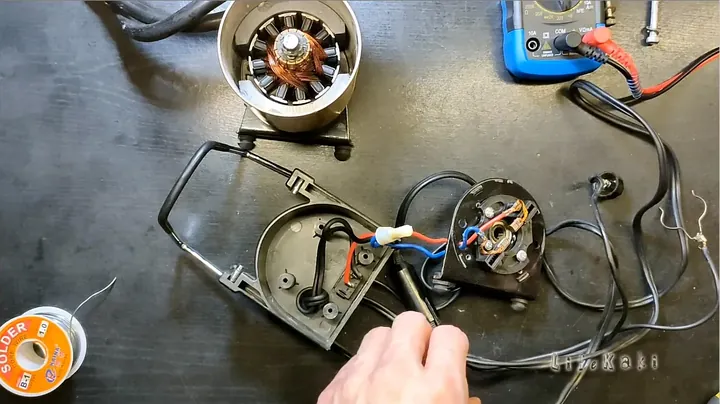
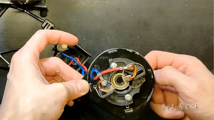
Lower the pump head and motor into the lower cradle. Watch the wiring — the harness has to sit in its guide channels or the casing halves will pinch the copper when you close it. Rubber isolator pads on the motor frame need to drop into their chassis pockets. Miss one and the cylinder tilts, the piston wrist pin binds against the bore, and you’re pulling it apart again. Check the rocker switch moves freely without rubbing on the shell cutout.
Securing the Internal Motor Mounts
Metal retaining straps hold the motor against piston vibration. Thread the retaining screws into the plastic bosses by hand until the heads seat. Do not use a powered driver here — you’ll strip the soft bosses out. Hand snug plus an eighth turn is plenty. Check the wiring harness clears the rotating counterweight wheel. Spin the crank disk with your thumb. Should turn freely. No drag.
Closing the Casing
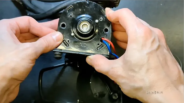
Bring the two shell halves together. Should be a flush seam all the way around. If it resists near the handle, stop and check for caught wires — don’t force the clam shut. Set each screw into its original boss. Reverse-turn slightly until you feel the thread drop into the existing lead, then tighten in a diagonal pattern so the clamshell clamps evenly. Housing feels rigid again.
Securing Hose Fittings and Cord Grommet
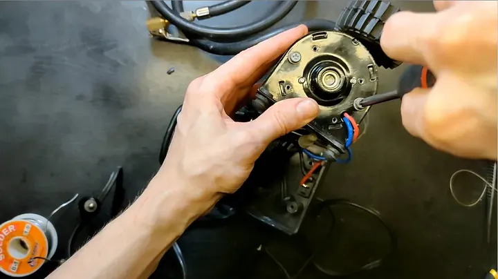
Seat the rubber cord grommet back in the casing notch. That boot takes the bending load when you drag the cord around a driveway. Thread the braided high-pressure hose back onto the pump discharge port. Check the O-ring inside the Schrader chuck. If it’s cracked or misaligned, the thing leaks air faster than it can deliver. Fittings look good.
Cleaning the Hose and Exterior
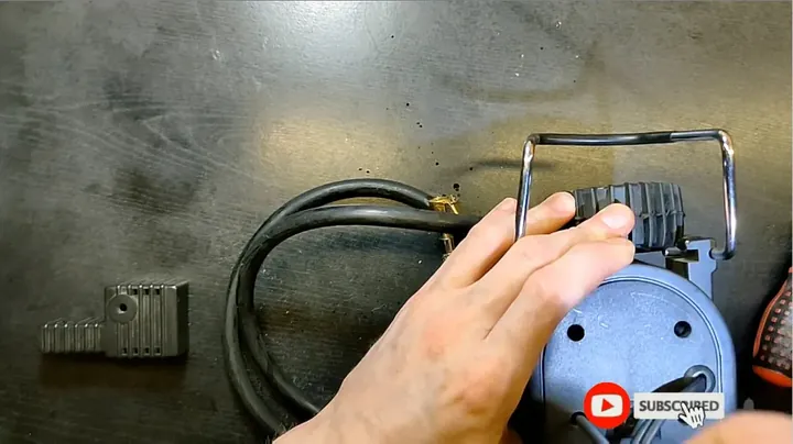
Wipe down the rubber hose and plastic shell. Built-up grit and oil film hide cracks. Run your fingers along the hose looking for ozone rot near the brass ferrule. A burst hose at 35 PSI is a horror show in a small garage. Blow low-pressure air through the nozzle chuck to clear grit around the valve pin. Tool maintenance now saves field failure later. Time for live voltage.
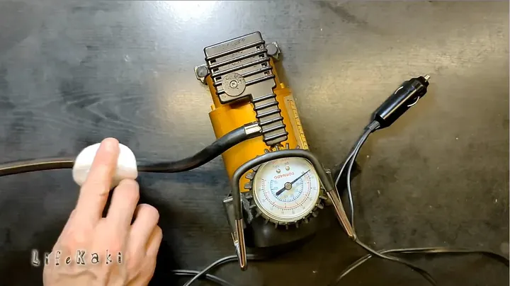
Live 12V Power-Up
Hook it up to a variable 12V bench supply so you can watch current draw without flattening a car battery. Hit the rocker switch. Motor fires up with an even hum. Listen to the pitch — steady, no gear rattle, no hunting rpm. Rubber pads kill the vibration like they should. Bench meter settles between 8 and 10 amps free-flowing. Right in spec.
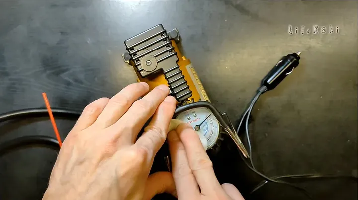
Pressure Test and Gauge Check
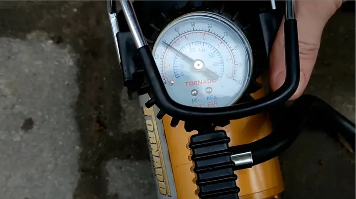
Block the chuck. Now the piston actually has to work against the cylinder check valve. Gauge sweeps past 20, 30, holds true at 45 PSI. Motor deepens into a heavy working thrum. Current stays stable — no bench breaker tripping. Lay your palm over the repaired wire entry. Plastic stays cool. No voltage drop, no smoke, motor never stalls. Crack the release valve to vent head pressure. Inflator’s back in service.
⚠️ CAUTION: SAFETY WARNING!
Disconnect the 12V power completely before opening the housing. Soldering iron tips hit 350°C — that’s a serious burn. And never run these compressors continuously against a blocked outlet past their rated PSI. The cylinder will fail.
Summary & Tips
Don’t scrap a dead 12V compressor before checking the wire behind the strain boot. A 20-minute solder job and a few inches of fresh wire and this one’s back to work — cost, pennies in solder and heat shrink. Clean the copper, pre-tin both surfaces, secure the wiring. Done.
📋 FAQ
❓ Why does my car compressor keep blowing the cigarette lighter fuse?
Usually a short inside the 12V male plug or the strain collar — chafed insulation touching metal. Less often: the cylinder or crank linkage locked up, stalling the motor and pulling way more current than the fuse can handle.
❓ Can I use electrical tape instead of heat shrink?
No. Motor heat and chassis vibration make vinyl tape adhesive slip. Next thing you know, a live terminal is exposed. Polyolefin or marine heat shrink is what you want — permanent insulation and strain relief.
❓ Can I run this off a 12V 2A wall adapter?
Nope. Direct-drive DC compressors pull 10-14 amps under cylinder pressure. A 2-amp supply will trip its internal overcurrent protection instantly — if you’re lucky. If you’re not, it cooks the adapter.
Disclaimer: All tools and gear used in this guide were bought with my own money so the review stays honest. Some links are affiliate links — I get a small cut if you buy through them, at no extra cost to you.
🛒 Useful Links & Products
Electric Soldering Iron
🛒 BUY ON ALIEXPRESS




Leave a Reply