Got this 32-inch Samsung LCD sitting flat on the workbench. Audio comes through fine, but the screen stays completely black. Traced it down to a dead backlight module. So the plan is simple: strip the chassis down to bare metal and swap in fresh LED strips.
Author: LifeKaki
⚡ Quick Guide: Samsung TV Backlight Replacement in 8 Steps
- Unplug the TV and clear a clean workbench space.
- Remove back cover screws and pop the clips off. Disconnect ribbon cables and secure the main board.
- Carefully lift out the fragile LCD matrix panel.
- Unscrew and swap the faulty LED backlight strips.
- Mount the replacement LED module securely.
- Reassemble the frame and reconnect all cables.
- Power up and verify the screen is back.
📋 In This Article
- Technical Specifications
- Tools & Materials — what you need
- Initial Prep and Flashlight Test
- Removing the Rear Casing
- Unplugging Cables and Securing Boards
- Extracting the Faulty Backlight Module
- Installing New LED Strips
- Reattaching the LCD Matrix and Frame
- Securing the Back Casing
- Final Power Test and Verification
📊 Technical Specifications & Components
| Model Series | Samsung UE32ES6100W (compatible with UE32ES6710, UE32ES6800, UE32ES6720S, UE32ES5500) |
| Symptom | Audio works normally, display remains dark or black |
| Diagnostic Test | Flashlight test reveals faint image on LCD panel |
| Backlight Type | LED strips along the edge/matrix array |
📊 Project Overview & Costs (USA Market)
🔧 Difficulty Level: Moderate / Medium bench assembly
⏱️ Time Investment: DIY: 60-90 minutes | Pro bench tech: 30 minutes
💰 Professional Service Cost: $120 – $180 (estimated bench labor and replacement hardware)
💡 Verdict: Fixing the backlight yourself saves around $140 in shop labor. Basically pays for the tools you’ll keep using.
Tools & Materials Used
🔧
Screwdriver Set For Smartphone
AliExpress 🛒
🔧
DT9205A Digital Multimeter
AliExpress 🛒
🛠️
BUY ON ALIEXPRESS 🛒
Recommended
Automotive Repair Tool Set
Step-by-Step Backlight Replacement & Testing
Initial Prep and Flashlight Test
First step: kill the AC power at the wall and clear a big stretch of rubber matting on the bench. A black screen with working audio is the classic LED backlight failure signature. Aim a bright inspection flashlight straight at the front polarizer and look for faint menu shapes floating under the surface. No point rushing this optical check — verify the LCD driver logic first so a good board doesn’t get pulled for nothing. Sketch the chassis outline on cardboard and poke each screw through in order so thread lengths never get mixed up. Grab a magnetic precision driver and line up the bits before cracking the rear seam. Teardown starts here.
Removing the Rear Casing
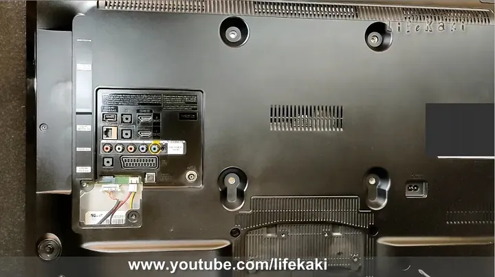
Back out every perimeter screw holding the rear plastic shroud to the internal chassis. Wedge a nylon spudger along the seam and pop the molded clips one at a time — no chewing up the soft plastic edges. Never rip the back panel away abruptly. Plenty of production runs route low-profile speaker leads right to the mounting posts. Lift the cover straight up and set it on a foam pad out of the way. Hit the metal sheet with an antistatic vacuum tip to clear the settled lint and dust. Snap a quick reference photo of the wiring and board layout before anything moves. Good shop habits stop stray shorts later.
Unplugging Cables and Securing Boards
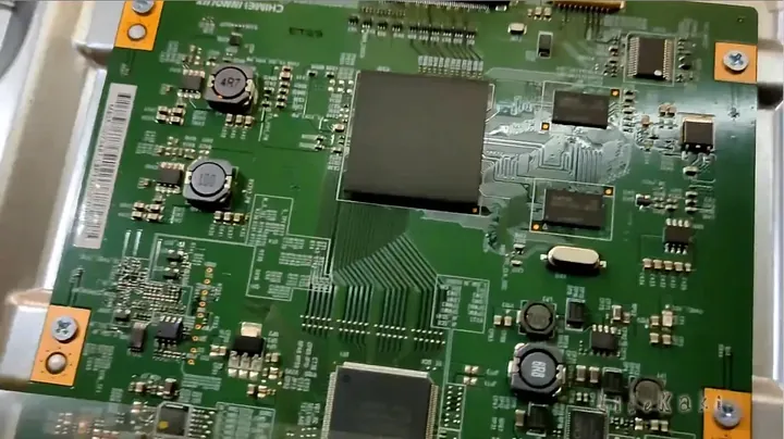
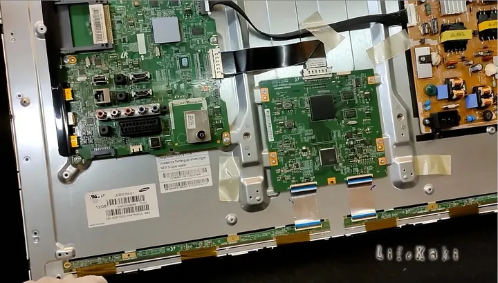
Flip open the tiny locking bails on the ribbon sockets between the main logic board and the panel. Tack the loose PCBs down with low-tack tape — no swinging boards, no fractured solder traces. Lifting out the bare glass matrix demands steady hands and deliberate motion. The substrate is exceptionally thin and bends under its own weight. One uneven twist means hairline fractures and a dead panel. Take minutes, not seconds, easing the LVDS ribbons out of their T-CON sockets. Confirm every latch is fully cleared before lifting anything off the metal frame.
Extracting the Faulty Backlight Module
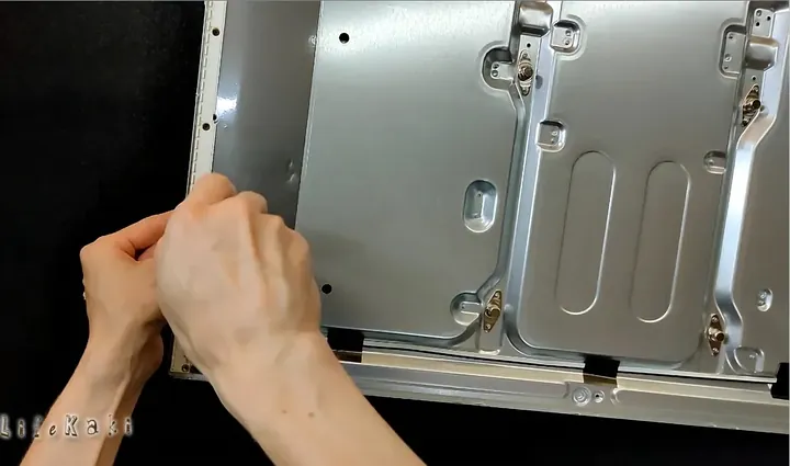
Disconnect the primary harnesses feeding the high-voltage LED driver board. Depending on the chassis revision, factory backlight runners are held with either miniature screws or high-bond thermal tape. Back out every tiny fastener and ease the warped strips off the aluminum tray with a dull pry bar. Cross-check the silkscreened part codes on the new strips against the original model stamps before swapping. Scrub the bare metal channel clean of dried thermal tape residue with a rag soaked in 99% isopropyl alcohol — the new strip has to sit dead flat. Direct contact with the aluminum base is what pulls heat away from the diodes.
Installing New LED Strips
Align the new LED strip assemblies straight into the factory guide channels where the dead ones sat. Press the rails down firmly along the whole run to set the thermal adhesive, then drive home the miniature screws down the channel. Tuck the power harness leads back through the molded clips so they don’t get pinched under the heavy diffuser sheets. Run a quick voltage test across the circuit — every diode should light with the same color and brightness before the diffusers go back on. Replace the plastic diffuser lenses, reflective backing sheets, and internal bezel brackets in reverse order of removal.
Reattaching the LCD Matrix and Frame
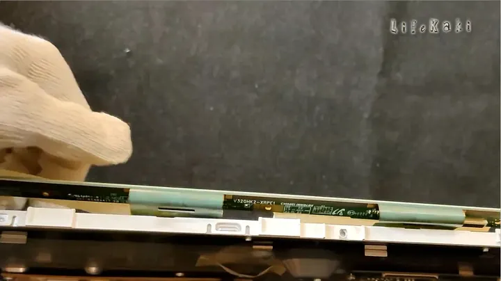
Guide the fragile glass matrix back onto the molded corner stops inside the outer bezel. Check the peripheral rubber cushioning strips — the glass has to sit perfectly square without binding anywhere along the lip. Reinsert the flexible ribbon cables straight into the T-CON sockets and snap the locking flaps down until they click. Position the stamped steel shield back over the logic board and run all the mounting screws down snug. Sweep a dry microfiber towel along the internal edges to catch stray dust and fingerprints. Everything seated solid.
Securing the Back Casing
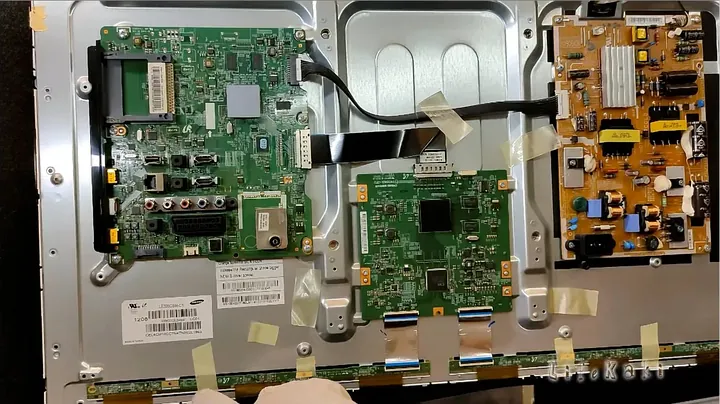
Press the plastic rear casing back onto the main chassis, working around until every perimeter latch clicks into place. Thread the exterior screws into their original positions — start near the central structural mounts and fan out toward the corners. Light touch on the driver handle. The plastic boss threads strip fast if you lean on them. Run a finger along the exterior seam to verify the shells meet flush without pinching any internal harnesses. Lift the finished chassis and give it a gentle test shake. No rattles anywhere.
Final Power Test and Verification
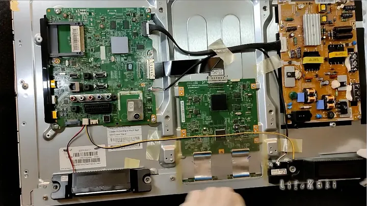
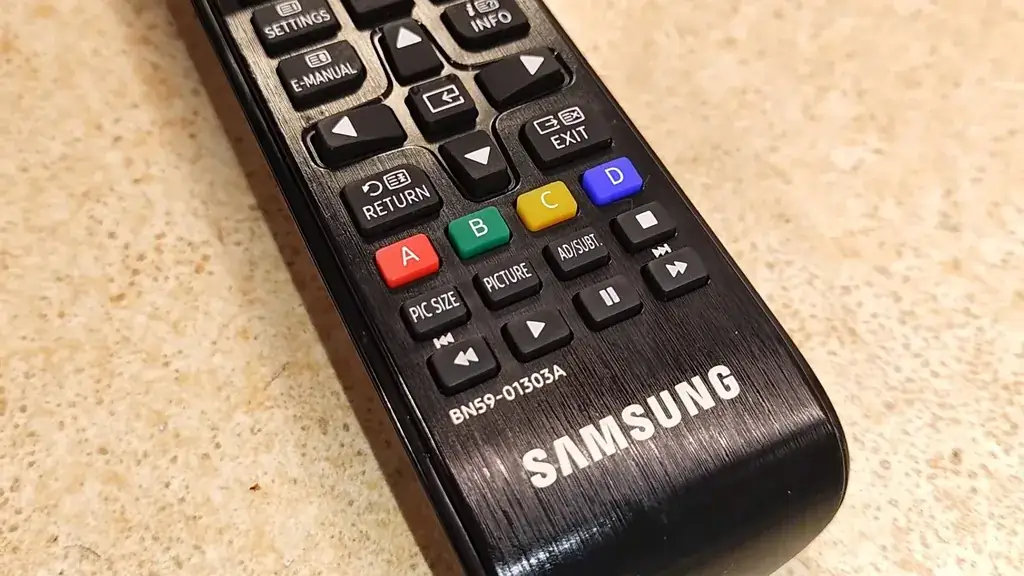
Plug the mains cord into the wall and press power on the remote. The bright Samsung boot logo appears instantly with uniform luminance and balanced contrast. Sound and display now sync perfectly, no flicker anywhere. A uniform panel with clean edge-to-edge lighting confirms a successful install. Spare hardware goes in the bench bin. Television goes back on its pedestal. Job complete.
⚠️ CAUTION: SAFETY WARNING!
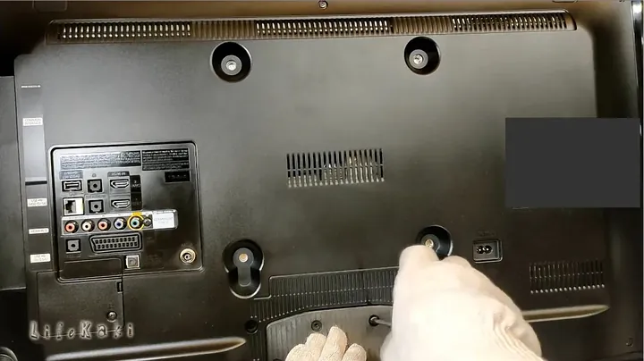
Kill AC power before disassembly. High-voltage capacitors in the power supply keep a dangerous residual charge after unplugging — bleed them before touching anything inside.
Summary & Tips
Digging into a flat-panel takes patience, but swapping out bad LED strips saves an otherwise scrapped TV for a few dollars in parts. Keep the bench clear of debris the whole time — handling raw LCD glass leaves zero margin for careless moves.
📋 FAQ
❓ How do you diagnose a backlight failure on a Samsung TV?
Audio works, channels switch, but the screen stays black. Shine a bright flashlight at the front LCD surface — if you can see faint menu shapes moving under the glass, the LED strips are dead. That rules out a blown mainboard.
❓ Can you replace a single dead LED instead of the whole strip?
Technically yes — you can jumper or solder in a new diode. But the ones next to it usually fail soon after from the same heat damage. Swapping the whole strip keeps voltage consistent and saves you from tearing the panel apart twice.
❓ How risky is it to lift out the bare LCD panel?
It’s the riskiest part of the whole job. The unframed glass has no structural rigidity — it flexes under its own weight. A clear work surface, suction cups, and a slow, even lift are what keep it in one piece.
Disclosure: All tools and diagnostic gear used in this guide were bought with my own money so the review stays honest. Some links are affiliate links — I get a small cut if you buy through them, at no extra cost to you.



Leave a Reply