This article details a WiFi repeater repair project, specifically troubleshooting a dead internal AC-to-DC converter rather than a damaged mainboard. The wall-plug device on the workbench is completely unresponsive, showing no indicator lights and broadcasting no signal. Instead of discarding the unit, this guide demonstrates how to open the housing, probe the voltage rails, and splice in a new power board to restore its function.
Author: LifeKaki
⚡ Quick Repair Overview
- Inspect the repeater housing and locate the seam split line.
- Carefully pry apart the plastic halves without snapping internal retaining tabs.
- Examine the main Wi-Fi logic board and integrated step-down power section.
- Probe input and output voltage rails using a digital multimeter set to DC mode.
- Verify zero voltage output from the failed onboard power supply.
- Desolder the dead converter lines from the repeater logic board pads.
- Prepare the replacement power adapter leads and tin the copper wire ends.
- Solder the replacement power supply leads, strictly observing correct polarity.
- Secure the replacement module and fasten the internal board screws tightly.
- Plug into mains power and verify functional status LEDs and a stable boot cycle.
📋 In This Article
- Technical Specifications
- Tools & Materials, what you need
- Visual Inspection of the Repeater Assembly
- Examining the Internal Circuit Board Layout
- Confirming Power Supply Failure under Load
- Prepping and Tinning Replacement Power Lines
- Mounting Boards and Fastening Screws
- Final Bench Testing and Network Verification
📊 Device Specifications and Operating Parameters
| Device type | Wall plug wireless repeater / range extender |
| Input AC voltage | 100-240V 50/60Hz |
| Target DC supply voltage | 5V regulated |
| Core failure mode | Blown switching transformer / no secondary DC output |
| Enclosure fastening | Ultrasonic seam with internal clips and central screw |
📊 Project Overview
🔧 Difficulty Level: Medium
⏱️ Time Investment: DIY: 35-50 mins | Pro: 15 mins
This repair saves about in technician fees and keeps functional hardware out of the landfill.
Tools and Components Used
• Replacement Power Supply Module
• Digital Multimeter with Test Probes
• Rosin Core Solder Wire
• Plastic Pry Opening Tool
🔧
Electric Soldering Iron
AliExpress 🛒
🔧
Screwdriver Set For Gadgets
AliExpress 🛒
🛠️
BUY ON ALIEXPRESS 🛒
Recommended
Replacement power supply used
Step-by-Step Power Supply Replacement Guide
Visual Inspection of the Repeater Assembly
Examine the faulty hardware’s sealed casing. Most plug-in range extenders use friction-fit latches or light ultrasonic welding along the plastic perimeter. Inspecting the seams reveals the best points for inserting a wedge tool without damaging the outer shell. Check closely around the integrated AC prongs for any hidden fasteners under label stickers.
Trapped heat frequently damages the miniature switching power supplies within these compact units. Poor ventilation causes electrolytic filter capacitors to dry out prematurely and fail. A quick look at the external ventilation slots confirms whether excessive dust buildup contributed to internal overheating. The internal board layout and components, as shown in Frame 1, appear intact, indicating a component-level problem.
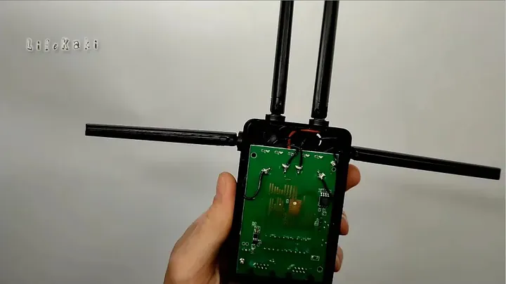
Splitting the Plastic Housing Apart
Disassembling the board (Frame 2) requires steady, even pressure along the parting seam. Sliding a rigid plastic spudger into the gap releases the internal locking tabs one by one. Work carefully around the perimeter to avoid cracking the brittle casing. Once the perimeter releases, gently lift the top cover away from the base assembly. Take care not to tear delicate copper antenna traces or internal ribbon wiring that might link the LEDs to the front panel. Keep track of how the light pipes align with the circuit board status indicators during disassembly. The internal electronics are now exposed for diagnostic probing.
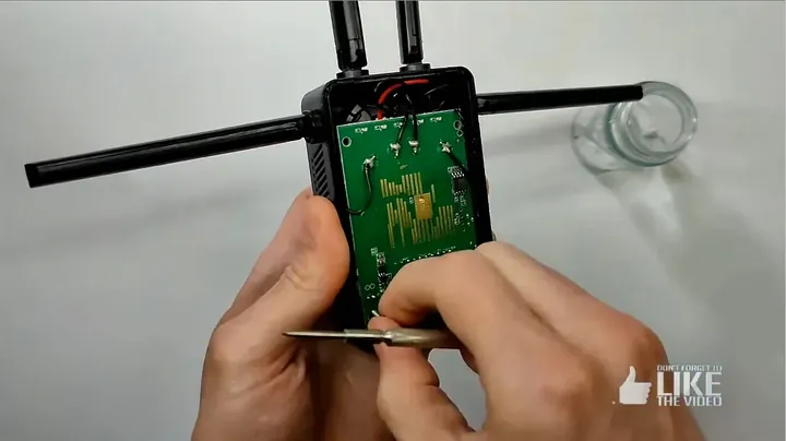
Examining the Internal Circuit Board Layout
The device’s board (Frame 3) reveals a compact design with two sections: a primary AC-DC conversion circuit and a logic board. The high-voltage side converts line power down to low DC voltage, typically 5 volts or 12 volts, depending on the radio chipsets. Examining the traces on both components shows no obvious burn marks, swollen capacitors, or carbon scoring across copper tracks.
This suggests the fault is within the integrated power controller or primary winding. Note the pair of flexible wires bridging the power board directly to the logic board supply pads. Tracing these connections indicates exactly where supply rails feed operating current into the SoC. Keeping these points clean makes multimeter verification faster. The next step is instrument confirmation.
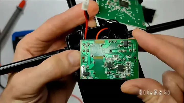
Measuring DC Voltage Rails with a Multimeter
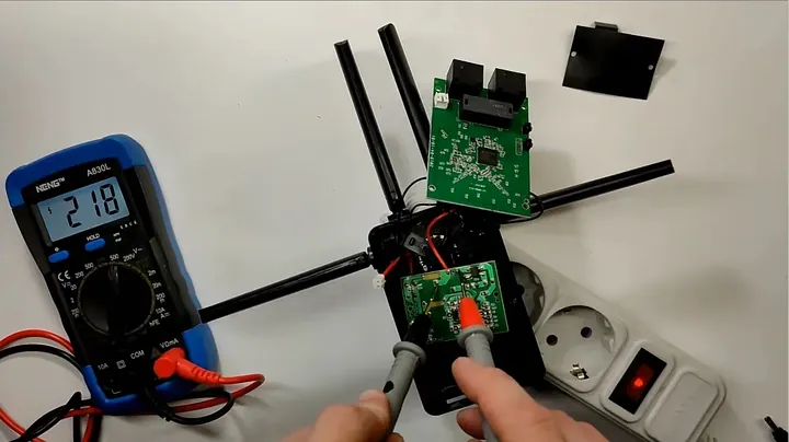
Measuring voltage with a multimeter on the board (Frame 4) validates the power delivery. Power up the circuit safely, using an isolation transformer or a protected socket. Switch the digital multimeter dial to the DC voltage range, selecting a twenty-volt maximum scale. Press the black ground probe against the negative board ground plane while touching the red probe to the positive output rail. The digital display shows essentially zero volts, fluctuating near background line noise. This flatline reading indicates an open circuit on the secondary conversion stage. Without steady DC power, the main radio controller cannot boot. The onboard power supply module is dead.
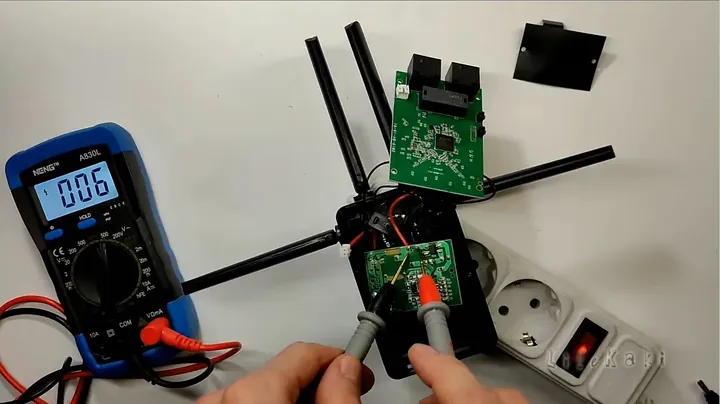
Confirming Power Supply Failure under Load
Check other filter nodes to ensure no secondary bypass capacitor is shorting the rail to ground. Placing the multimeter leads across the smoothing electrolytic capacitor terminals confirms an absence of any potential difference. If the main logic board had a dead short, the power converter would tick or pull high current through a current-limiting resistor.
Here, the supply is completely dead without any output waveform or switching activity. High-voltage side resistors frequently blow open during minor grid surges, permanently isolating the PWM driver. Attempting component-level rework on such inexpensive sub-boards wastes valuable time. Replacing the entire sub-assembly with an isolated replacement board offers the cleanest and most reliable solution.
Desoldering Old Power Leads from the Board
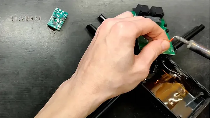
Soldering wires onto the board with a soldering iron (Frame 6) disconnects the defective power module. Heat the soldering iron to approximately three hundred and fifty degrees Celsius. Apply a tiny dab of fresh rosin flux onto the factory solder pads where the power leads anchor. Wet the soldering tip with a bead of solder.
Touch the iron tip against the existing solder puddle and pull the stranded wire away once the alloy turns molten. Work quickly, as overheating small through-hole pads can lift copper traces off the fiberglass substrate. Clean off any residual alloy using copper desoldering braid or a manual suction pump. The logic board contact eyelets are now clean and ready for the replacement supply wiring for this WiFi repeater repair.
Prepping and Tinning Replacement Power Lines
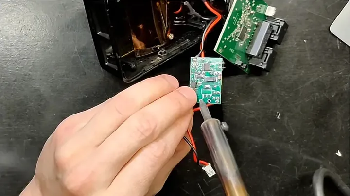
Soldering power supply wires (Frame 7) begins the installation of a fresh switching adapter. Trim the output wires to custom lengths that fit neatly inside the cramped shell. Strip approximately two millimeters of PVC insulation off the positive and negative leads using automatic wire strippers. Twist the fine copper strands tightly clockwise to prevent frays that might short out against adjacent components.
Coat the bare conductor tips with liquid flux and touch them with a tinned iron tip until solder wicks completely through the copper bundle. This ensures immediate bonding when joining the leads to the motherboard pads. Double-check the color-coding to maintain correct positive and negative polarity. Incorrect polarity on high-speed logic chips destroys flash memory and processing cores in milliseconds.
Soldering the Replacement Module to the Logic Board
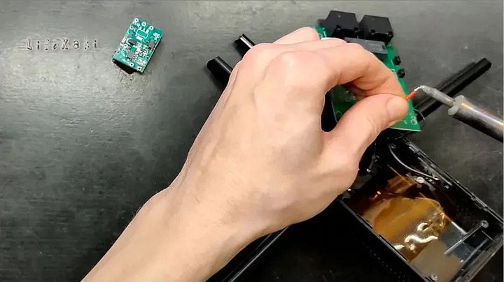
Soldering contacts on the board (Frame 8) secures the new power module. Thread the pre-tinned positive lead directly into the corresponding VCC pad on the logic board. Apply the hot soldering iron tip for no more than two seconds while introducing a small dab of rosin core solder. The molten alloy forms a clean, concave fillet around the wire strand, signaling a reliable mechanical and electrical bond. Repeat the exact same soldering procedure on the adjacent ground pad. Give both wires a light physical tug once the joint solidifies to verify no cold solder weakness. Trim off any excess wire ends poking through the reverse side of the board to prevent contact shorts against the casing wall.
Mounting Boards and Fastening Screws
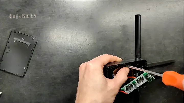
Reassembling the hardware requires routing internal wires away from sharp housing edges and thermal sinks. Seat the replacement power supply securely into the designated cavity inside the base enclosure. Place the logic board into its alignment tabs, ensuring the exterior antenna connections and front panel buttons sit square. Use a precision screwdriver to drive the internal fastening screw into the central mounting point. Snug the screw until it seats firmly. Dress all loose wiring neatly along the perimeter recesses so no insulation gets pinched when closing the clamshell halves. Snap the top housing cover over the base until all perimeter latches lock together with audible clicks.
Final Bench Testing and Network Verification
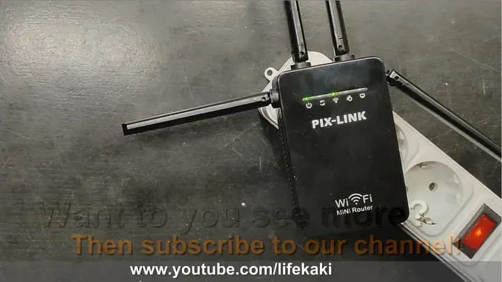
The finished, assembled router working and lit up (Frame 10) verifies the repair’s success. Plug the device into an outlet and observe the status indicators immediately illuminate on the front panel. The power LED lights up solid, followed shortly by the blinking initialization pattern of the wireless controller.
Within thirty seconds, the radio module broadcasts its default network SSID, proving the microprocessors booted successfully. Connecting a smartphone or laptop to the wireless broadcast confirms stable signal throughput and full access to the configuration portal. Operating temperature across the plastic exterior remains comfortably cool under sustained network load. The repeater is completely restored to service without purchasing a replacement unit.
⚠️ CAUTION: SAFETY WARNING!
Working with open mains electrical adapters involves dangerous alternating current voltages up to 240 volts. Always unplug the unit from AC mains power before touching components, desoldering wires, or inspecting traces inside the enclosure.
Summary & Tips
Replacing a failed internal power module is far more practical than discarding a dead network extender. As long as the logic board survived without shorted silicon, an inexpensive five-volt supply board restores original wireless functionality in under an hour. Double-check wire polarities and solder joints before snapping the casing shut.
📋 Frequently Asked Questions (FAQ)
❓ How do I determine the correct voltage for my repeater’s power supply?
Check the labeling on the original circuit board or search the main chip part number. Most small range extenders run on a regulated 5V DC line, though some larger dual-band units use 12V. Checking the voltage rating of the largest filter capacitor also provides a solid clue.
❓ Can I use an external 5V USB charger instead of an internal module?
Yes, this is an option. If a tiny board that fits inside the shell is unavailable, drill a small hole in the casing and solder a prepared USB cable directly to the positive and ground logic pads. Plugging it into any standard phone wall charger will allow it to function.
❓ What caused the original power supply to fail?
Heat is the primary cause. These tiny adapters run continuously inside plastic housings without ventilation, which over time degrades cheap electrolytic capacitors. Grid power spikes can also damage the fragile primary switching transistor unexpectedly.
Disclosure: this post contains affiliate links. If you buy through them, we may earn a small commission at no extra cost to you.
🛒 Useful Links & Products
Replacement power supply used
🛒 BUY ON ALIEXPRESS




Leave a Reply