I’m taking a close look at this digital TV signal amplifier to determine if it’s truly worth the effort to install for better reception. We’ll go through the complete hook-up procedure, and then I’ll crack it open for a thorough internal examination. My goal is to see exactly what’s inside and assess whether it’s built for durability or if it’s just another cheaply made device.
Author: LifeKaki
⚡ Quick Guide: Boost Your TV Signal & Peek Inside
- Unbox the digital TV signal amplifier and check its components.
- Inspect the coaxial and USB connectors for any damage or flaws.
- Connect the amplifier’s coaxial input to your TV’s antenna port.
- Plug the amplifier’s USB cable into a free USB port on your TV or a power adapter.
- Monitor your TV screen for signal improvement and stability after connection.
- Carefully pry open the amplifier’s glued plastic casing using a utility knife.
- Separate the two halves of the housing to access the internal components.
- Gently remove the printed circuit board (PCB) from its housing.
- Examine the soldering quality, signal routing, and main microchip on the PCB.
- Reassemble the amplifier casing, using adhesive to secure the halves together.
📊 Technical Specifications & Components
| Power Input | 5V (via USB) |
| Connector Type | Coaxial F-type, USB-A |
| Coaxial Impedance | 75Ω |
📊 Project Overview
🔧 Difficulty Level: Medium
⏱️ Time Investment: DIY: 30-40 mins | Pro: 15-20 mins
Tools & Materials Used
• Digital TV Signal Amplifier
• Coaxial F-type Connectors
• 75Ω Coaxial Cable
🔧
Makita D-65713 Utility Knife Snap-Off Easy
AliExpress 🛒
🔧
Hot Melt Glue Gun
AliExpress 🛒
🛠️
BUY ON ALIEXPRESS 🛒
Recommended
TV Amplifier
Step-by-Step Assembly & Testing
Unboxing and Initial Inspection
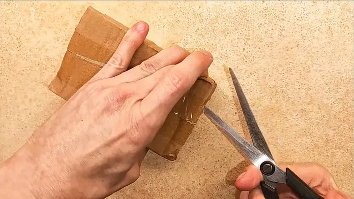
First order of business, I’m opening the packaging for this digital TV antenna signal amplifier. I always do a quick visual check of the box itself to ensure no damage occurred during shipping. Inside, I carefully remove the amplifier, taking a moment to assess the feel of its plastic casing. This initial touch often gives me a sense of the overall construction quality. I’m looking for any obvious flaws, such as cracks, loose components, or imperfect molding, before I even consider plugging it in. The unit is compact and feels quite light in my hand. Everything appears to be in satisfactory condition, so I’m ready to move on.
Connector Inspection
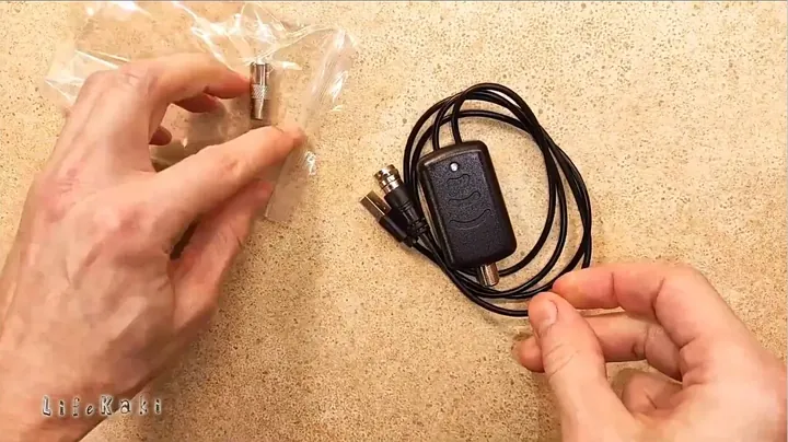
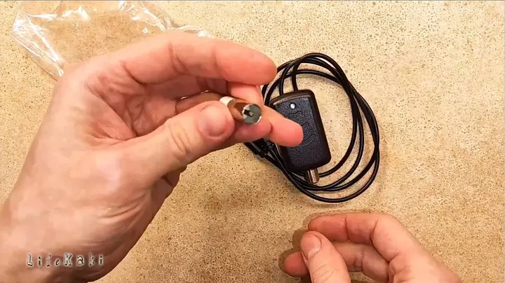
Next, I focus on the amplifier’s connectors. There’s a coaxial input, typically an F-type, for the antenna signal, and a USB port for power delivery. I’m carefully examining both, checking for any bent pins on the USB or any signs of corrosion within the coaxial barrel. A pristine connection is critical for efficient signal transfer, so I want to avoid any potential issues from the outset. The coaxial port feels securely mounted, without any noticeable play, and the USB connector appears to be a standard design. It’s engineered to accept a 5-volt power input, which is common for such devices. Everything seems sufficiently durable for regular usage, which is a positive indicator.
Connecting to the TV’s Antenna Input
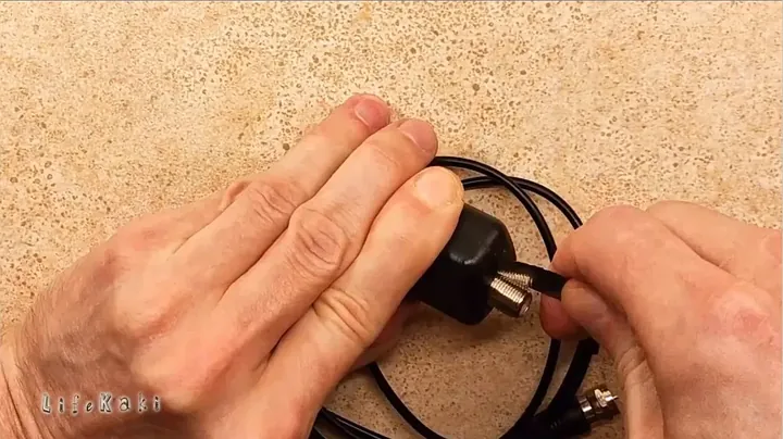
it’s time to connect the amplifier. First, I take the coaxial cable from the antenna and screw it into the amplifier’s input port. Then, I connect another coaxial cable from the amplifier’s output to the antenna input on the back of the television. I make sure these connections are finger-tight, but I avoid overtightening to prevent damaging the threads. I’m feeling for a firm, secure mechanical connection, ensuring there’s no looseness. This configuration routes the antenna signal through the amplifier first, providing a boost before it reaches the TV’s tuner. It’s a fairly simple process, really, but proper connections are essential.
Powering Up and Initial Signal Check
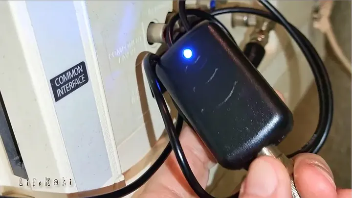
With the coaxial cables secured, the next step involves energizing the amplifier. I’m plugging the USB cable into an available USB port on the back of the television. If a spare port isn’t accessible on the TV, a standard 5-volt USB wall adapter will serve the purpose just as well. Upon receiving power, a small blue indicator light on the amplifier illuminates, confirming its operational status. This visual confirmation is quite helpful. I then switch the TV to its antenna input to evaluate the signal. My primary focus is on a stable picture, devoid of any flickering or pixelation. The on-screen signal appears to be consistently strong, which is precisely the desired outcome. This verifies that the amplifier is active and performing its function.
Observing Signal Improvement
With the amplifier connected and operational, I am now carefully observing the television screen for any discernible enhancements in signal quality. The objective isn’t merely to receive a picture, but to achieve a distinctly *improved* picture. I’m looking for greater image sharpness, clearer audio, and a reduction in digital artifacts or signal dropouts, particularly on channels that previously exhibited weakness. The improvement can sometimes be subtle, but often, it makes a substantial difference, transforming an previously unwatchable channel into one that is perfectly clear. Ultimately, the effectiveness hinges on the strength of the existing signal the amplifier has to work with, but a significant boost is usually transformative.
Opening the Glued Casing
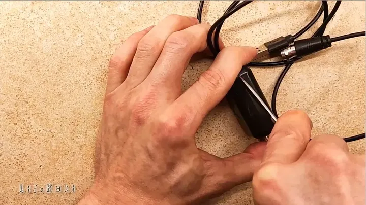
it’s time for the teardown. This plastic housing isn’t really made for easy disassembly; it’s factory-glued shut, which is pretty typical for these small electronic devices. I’m taking my utility knife and carefully running it along the seam where the two halves meet. You have to be gentle here, applying steady, even pressure to break that adhesive bond without slipping or scratching the plastic too badly. I’m taking my time, slowly working the knife blade into the gap, trying to find the weakest points of the glue. It’s a slow process; rushing it would just result in broken tabs or gouged plastic. You’ll feel the resistance as the glue starts to give way. Clearly, this wasn’t designed with repair in mind.
Separating the Housing Halves
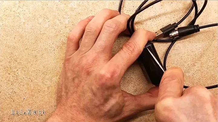
With the initial seal breached, I continue to work my way around the entire perimeter of the casing. This requires a delicate balance: applying sufficient force to separate the glued halves without cracking the somewhat brittle plastic. I’m using the utility knife to gently pry the two sections apart, listening carefully for any creaking sounds that might indicate areas of stress. Sometimes, once some progress is made, it’s helpful to insert a wider prying tool into the gap to better distribute the force. The objective is to achieve a complete separation of the halves without causing irreparable damage. It’s quite a challenge, as these units are not designed for easy access, but with patient effort, the plastic eventually yields, revealing the internal components. You can’t just rip it open.
Extracting the Printed Circuit Board
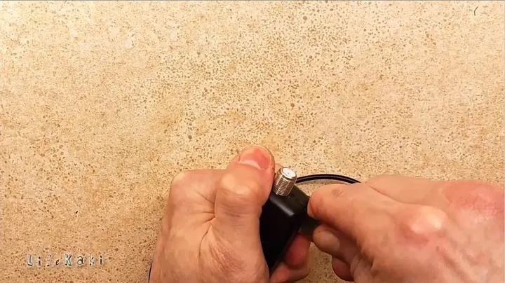
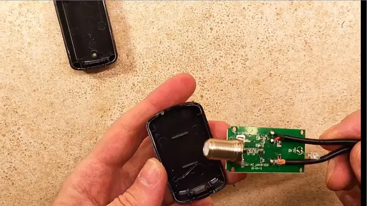
Once the casing is completely open, the next move is to carefully remove the printed circuit board (PCB) from its housing. Often, these boards are held in place by friction or by small plastic retention tabs. I’m gently wiggling the board, checking for any hidden fasteners or screws that might still be securing it. It’s crucial not to bend or snap the board, as it’s the core of the amplifier’s functionality. I also remain aware of any tiny wires or connectors that could be attached, taking care not to accidentally dislodge them. The board typically slides out with minimal effort once all securing points are released. This step demands a delicate touch to avoid damaging the sensitive electronics. We’re almost ready for the detailed examination.
Printed Circuit Board Inspection
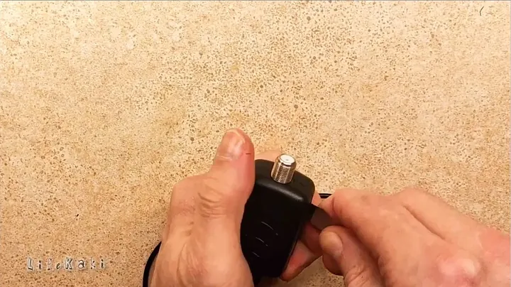
Now that the internals are exposed, it’s time for a proper examination of the printed circuit board. I’m closely scrutinizing the quality of the soldering—looking for clean, shiny joints versus any dull or irregular connections. I’m also tracing the signal pathways to understand the layout and how the components interlink. The main microchip, which serves as the amplifier’s central processing unit, is clearly identifiable. I’m checking for any visible manufacturing defects, such as cold solder joints, lifted traces, or components that aren’t mounted correctly. It’s a compact board, fairly typical for this kind of device, and the components appear to be arranged logically. This visual assessment provides a good indication of the overall manufacturing standards. It’s not a top-tier board, but it appears to be functional.
Reassembly
With the inspection completed, it’s time to reassemble this small amplifier. I’m carefully positioning the printed circuit board back into one half of the plastic casing, ensuring it aligns perfectly with the ports and any internal mounting posts. Then, I bring the two halves of the casing together, pressing them firmly along the original seam. Since this unit was originally sealed with adhesive, it won’t simply snap back into place. I’ll need a few small dabs of adhesive—a hot glue gun or even some glue will work—applied sparingly along the seam to secure it. You don’t want to use too much, just enough to hold it firmly. If you plan on doing this kind of teardown again, remember to keep this video handy for future reference. The case feels sturdy once the glue has cured.
Summary & Tips
Here’s the takeaway: This digital TV signal amplifier does what it claims—it boosts your signal. The internal construction is pretty basic; nothing extraordinary, but it functions as intended. If you’re dealing with a weak signal, connecting this amplifier is a straightforward solution. Just remember, it can’t create a signal from nothing, but for enhancing an existing one, it’s a reliable, practical piece of kit.
📋 FAQ
❓ Does a signal amplifier fix all reception issues?
An amplifier boosts existing signal. It does not generate signal where none exists. Prioritize antenna placement for optimal results.
❓ Is the internal build quality durable?
Internal construction features a standard compact circuit board, suitable for basic signal amplification. Maintain a dry environment to prevent corrosion and connection issues.
❓ What kind of power does this TV amplifier use?
Power is supplied via a standard 5V USB connection. It can be connected to a TV’s USB port or a USB wall adapter for operation.
Disclaimer: I purchased all tools for this guide with my own money to ensure an unbiased review. This post contains affiliate links, meaning I earn a small commission if you make a purchase at no extra cost to you.
🛒 Useful Links & Products
TV Amplifier
🛒 BUY ON ALIEXPRESS





Leave a Reply